A solid-state relay (SSR) integrated circuit that functions as a mechanical relay. it enables you to control high-voltage AC loads using DC Voltage control circuitry. it accomplishes this using infrared light as the 'contact, and a solid-state relay is just an Infrared LED and a photo-Triac sealed up in a small package.
AED 15.00
Description
The 5V Solid State Relay Module with 2 channels is an efficient electronic component designed to control high-voltage AC loads using DC voltage control. It operates using infrared light as the "contact" without any moving parts, making it durable and silent during operation. The module provides excellent electrical isolation between low-voltage control and high-voltage load sides, enhancing safety. With fast response times, low power consumption, and no mechanical contact, it offers increased precision and reliability in various applications, including home automation, industrial control systems, and robotics.
Package Includes:
- 1 x Relay Module 2 Channel SSR 5V DC To 240 AC Solid State Low Level
Features:
- High Current Capacity: The relay board is capable of controlling a single load of up to 2 amps at 240 V AC. This high current capacity makes it suitable for handling various appliances and equipment that require significant power.
- Versatility: The board is designed to handle different types of loads, making it suitable for various applications such as lighting, holiday displays, and other electrical devices.
- Easy Integration: Assembled and electrically tested, the relay board is ready for immediate use. Its plug-and-play nature ensures convenient integration into different projects and systems.
- Solid State Relays: The use of solid-state relays eliminates the need for mechanical contacts, resulting in silent operation and increased durability compared to traditional mechanical relays.
- Electrical Isolation: The relay board offers excellent electrical isolation between the control side (microcontroller) and the load side (appliances and equipment). This ensures enhanced safety and minimizes the risk of electrical shocks.
- Microcontroller Compatibility: The relay board is designed to be controlled directly by a microcontroller, allowing for seamless integration into microcontroller-based projects and automation systems.
- Low Power Consumption: The board's solid-state design results in low power consumption, making it energy-efficient and suitable for applications that require long-term operation.
- High Reliability: The relay board's fast response times and absence of moving parts contribute to its high reliability, reducing maintenance requirements and ensuring consistent performance.
Description:
The 5V Solid State Relay Module with 2 channels is a remarkable piece of electronic equipment that brings the benefits of solid-state technology to the world of relay control. Unlike conventional mechanical relays, solid-state relays (SSRs) operate without any moving parts, using infrared light as the key element to control high-voltage AC loads with precision and efficiency. In essence, an SSR serves as an integrated circuit that emulates the functionality of mechanical relays, but with distinct advantages that make it a superior choice in many applications. By harnessing the power of infrared light, these solid-state relays effortlessly enable the control of high-voltage AC loads using lower-voltage DC control circuitry. Encased within a compact package, each SSR channel contains an infrared LED and a photo Triac, working together seamlessly to create a reliable switching mechanism. The advantages of utilizing solid-state relays become evident when comparing them to traditional mechanical relays. One of the key benefits is their silent operation, as they produce no noise or vibrations due to the absence of any mechanical contacts. Furthermore, SSRs boast an impressive lifespan, outlasting their mechanical counterparts by a considerable margin. This extended lifespan contributes to reduced maintenance requirements and increased system reliability. The 5V Solid State Relay Module's adaptability is equally noteworthy, as it effortlessly interfaces with digital control signals, making it easy to incorporate into various projects and systems. Its capability to control high-voltage loads using low-voltage DC control signals opens up a world of possibilities for applications in home automation, industrial control systems, robotics, and more.
Principle of Work:
The 5V Solid State Relay Module with 2 channels operates on a principle similar to an optocoupler, with the key difference being the use of an Opto-Triac to handle larger currents. The SSR is designed to function without any mechanical movement, making it a highly reliable and durable solution compared to traditional relays. The operation of the SSR begins with an LED component, also known as the transmitter, which emits infrared light when activated by a low-voltage DC control signal. This infrared light serves as the control signal and is directed toward the Opto-Triac receiver component, which acts as the receiver. The Opto-Triac is designed to handle large currents and is optically isolated from the control side of the circuit. When the infrared light from the transmitter reaches and "saturates" the Opto-Triac, it triggers the Triac to conduct electricity, effectively completing the circuit and allowing current to flow through the high-voltage load. This optically coupled system, relying on the photo-induced conductivity of the Opto-Triac, ensures that no physical contacts are used in the switching process. As a result, the SSR operates silently and without the wear and tear associated with mechanical relays, leading to a significantly longer lifespan. The advantages of the SSR system extend beyond its durability. Because it relies on solid-state components and the absence of mechanical contacts, it responds more quickly to the control system's triggers. This responsiveness is crucial in various applications that require rapid and precise switching, such as in industrial control systems or automation processes.
Pinout of the Module:

Input:
-
DC+: This pin is connected to the positive supply voltage, which should match the relay voltage rating. Ensure to provide the appropriate power supply according to the relay module's voltage requirement (e.g., 5V DC).
-
DC-: This pin is connected to the negative supply voltage (common ground). It serves as the ground reference for the entire module.
-
CH1: This is the signal-triggering terminal of the relay module. To control the first channel, apply a low-voltage DC signal (e.g., 0V to 5V) to this pin. When the CH1 pin receives an appropriate signal, it will activate the corresponding solid-state relay and control the connected load.
Output:
- Connect a load: The output terminals of the relay module are designed to connect a load with the following specifications:
- Maximum Current: 2 Amps
- Voltage Rating: Up to 240 VAC (Alternating Current)
- The module provides the capability to switch high-voltage AC loads, making it suitable for various applications where high-power control is required.
Applications:
- Relay Drive from External Contacts: The solid-state relay module can be used to interface with external contacts and provide electrical isolation when driving other relays or devices, making it an excellent choice for relay control systems.
- LED Series and Parallel Connections: The SSR's ability to handle high-voltage loads efficiently makes it suitable for driving series or parallel LED configurations, allowing for control and optimization of LED lighting systems.
- Home Automation: In home automation systems, the SSR module can be employed to control various electrical appliances, lighting, heating, and cooling systems, offering enhanced safety and responsiveness.
- High Current Load Switching: With its capacity to handle up to 2 amps of current at 240 V AC, the SSR module is ideal for switching high-current loads, making it applicable in power distribution and heavy-duty industrial applications.
- Electro-mechanical Relay (EMR) Replacement: The SSR module serves as a reliable and durable replacement for traditional electromechanical relays, eliminating the concerns related to mechanical wear and offering a longer lifespan.
- Automatic Test Equipment: In automatic test equipment setups, the SSR module can be utilized for precise control and switching of test signals, enabling efficient and reliable testing processes.
- Instrumentation Systems: The SSR's fast response times and electrical isolation make it suitable for precise control and switching in instrumentation systems, ensuring accurate data collection and measurement.
- Industrial Automation: In industrial automation scenarios, the SSR module plays a crucial role in controlling motors, heaters, pumps, and other high-power equipment, enhancing the efficiency and safety of industrial processes.
- Thermostats: The SSR module can be used in thermostat circuits to control heating or cooling elements in temperature control systems, ensuring precise and responsive temperature regulation.
- Programmable Logic Controllers (PLCs): For interfacing with programmable logic controllers, the SSR module provides reliable control over various industrial processes, contributing to the automation and optimization of manufacturing operations.
Circuit:
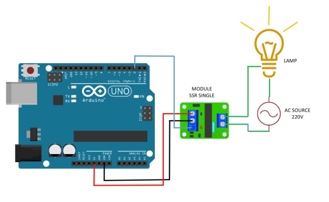
In this demonstration, we will alternate between turning on a 220V lamp for 1 second and then switching it off for 1 second in a blinking pattern.
Library:
This Module doesn't need a library to work.
Code:
This code is to control the state of a lamp connected to the digital pin 2 (D2) of the board. The purpose of the code is to make the lamp blink in a pattern of being ON for 1 second and then OFF for 1 second repeatedly:
void setup() {
  // initialize digital pin 2 as an output.
  pinMode(2, OUTPUT);

  // initialize the serial communication
  Serial.begin(9600);

  // Start with the lamp ON
  digitalWrite(2, HIGH);
}

// the loop function runs over and over again forever
void loop() {
  digitalWrite(2, LOW); // turn the lamp ON by making the voltage LOW
  Serial.println("Lamp ON");
  delay(1000);

  digitalWrite(2, HIGH); // turn the lamp OFF (HIGH is the voltage level)
  Serial.println("Lamp OFF");
  delay(1000);
}
void setup():
- This is the setup function that runs only once when the Arduino board starts up. It initializes the digital pin 2 as an output pin using
pinMode(2, OUTPUT). - Additionally, it starts the serial communication at a baud rate of 9600 with
Serial.begin(9600). Lastly, it sets the initial state of the lamp to be ON by setting digital pin 2 to HIGH usingdigitalWrite(2, HIGH).
void loop():
- This is the loop function that runs repeatedly as long as the Arduino is powered on. It contains the code to control the blinking pattern of the lamp. The code inside the loop consists of two main parts:
- a.
digitalWrite(2, LOW);: This line turns the lamp ON by making the voltage LOW on digital pin 2. In other words, it brings the voltage level of pin 2 to 0V, which activates the lamp. - b.
Serial.println("Lamp ON");: This line prints the message "Lamp ON" to the serial monitor. The serial monitor allows you to see the messages printed by the Arduino on your computer. - c.
delay(1000);: This line introduces a delay of 1 second (1000 milliseconds) before proceeding to the next line. This delay keeps the lamp ON for 1 second. - d.
digitalWrite(2, HIGH);: This line turns the lamp OFF by making the voltage HIGH on digital pin 2. In other words, it brings the voltage level of pin 2 to 5V, which deactivates the lamp. - e.
Serial.println("Lamp OFF");: This line prints the message "Lamp OFF" to the serial monitor. - f.
delay(1000);: This line introduces another delay of 1 second before the loop repeats, turning the lamp ON again and repeating the blinking pattern indefinitely.
Technical Details:
- Size: 24*32*21mm/0.94*1.25*0.82”
- Input Power: 5V DC (160mA)
- Input control signal voltage:
- (0-2.5V state low Relay OFF)
- (3-5V state high Relay ON)
- Voltage version 5V
- Static current 0mA
- Working current 12.5mA
- Trigger voltage 3.3-5V
- Trigger current 2mA
Resources:
Comparisons:
- While electromechanical relays (EMRs) and solid-state relays (SSRs) both serve the purpose of controlling electrical loads, they operate using distinct principles and have different characteristics.
- EMRs utilize coils, magnetic fields, springs, and mechanical contacts to switch the power supply, while SSRs rely on the electrical and optical properties of solid-state semiconductors, having no moving parts. This fundamental difference enables SSRs to perform input to output isolation and switching functions more efficiently and reliably.
- One notable advantage of SSRs is their ability to provide complete electrical isolation between input and output contacts, similar to EMRs. However, unlike EMRs, SSRs achieve this isolation without physical contacts, leading to enhanced durability and longevity. Their output functions like a conventional electrical switch, offering very high resistance when nonconducting (open) and very low resistance when conducting (closed).
- It is essential to note that while SSRs excel in driving AC loads, they are not designed to handle DC loads, unlike traditional relays that are versatile enough to work with both AC and DC loads. Additionally, EMRs can handle higher current capacities compared to SSRs, making them more suitable for certain high-power applications.
- you can check this item if you want more current.