100 and 240V AC voltages at up to 2A current and can be controlled by any 5V Controller such as an Arduino MCU Board or any other MCU. To protect against excessive current draw, a resistive type fuse is soldered to the module
AED 31.50
Description
The 4-Channel 5V Solid State Relay Module incorporates solid-state relay (SSR) technology to enable control over high-voltage AC loads using DC voltage control circuitry. Unlike mechanical relays, SSRs utilize an Infrared LED and a photo-Triac within a compact housing, allowing for efficient switching through infrared light. The module operates with a 5V input and offers four individual channels for enhanced load management. With its innovative design, the 4-Channel 5V Solid State Relay Module presents a modern approach to high-voltage AC load control, offering advantages in reliability and precision.
Package Includes:
- 1 x Relay Module 4 Channel SSR 5V DC To 240 AC Solid State Low Level
Features:
- Solid-State Technology: Leveraging solid-state relay (SSR) integrated circuits, this module offers a more reliable and durable alternative to traditional mechanical relays.
- Infrared Contact: Utilizes an Infrared LED and a photo-Triac as the 'contact' mechanism, enabling efficient switching of high-voltage AC loads through infrared light.
- Four Channels: Provides four independent channels for simultaneous control of multiple high-voltage AC loads, enhancing flexibility in load management.
- 5V DC Input: Designed to operate with a 5V DC input, making it compatible with various control circuitry setups.
- Efficiency: Eliminates mechanical wear and tear due to the absence of moving parts, resulting in reduced maintenance requirements and increased operational lifespan.
- Rapid Response: The use of infrared light for switching ensures quick response times, surpassing the speed of traditional mechanical relays.
- Longevity: Solid-state design guarantees extended operational life, making it suitable for applications requiring sustained and reliable performance.
- Precision Control: Offers accurate and repeatable switching, ensuring precise control over high-voltage AC loads.
- Compact Form Factor: Housed in a compact package, the module saves space while delivering advanced functionality.
- Wide Application Range: Suitable for a variety of applications including industrial automation, home electronics, renewable energy systems, and automotive control.
- Enhanced Safety: Reduced risk of arcing and sparking due to the absence of physical contacts, enhancing overall safety in operation.
- Isolation: Provides isolation between control and load circuits, contributing to improved system stability and protection.
- Temperature Tolerance: Designed to operate effectively within a specified temperature range, ensuring reliable performance even in varying environmental conditions.
Description:
The 4-Channel 5V Solid State Relay Module is a compact yet powerful device designed to revolutionize high-voltage AC load control. At its core, this module embraces the innovative concept of solid-state relay (SSR) technology, effectively bridging the gap between traditional mechanical relays and modern integrated circuitry. Much like its mechanical counterpart, a solid-state relay functions as a relay switch, enabling the control of high-voltage AC loads. However, what sets SSRs apart is their utilization of an ingenious integration of an Infrared LED and a photo Triac within a confined enclosure. This innovative approach allows for efficient switching through the use of infrared light, marking a departure from the physical contacts found in mechanical relays. A Solid State Relay operates seamlessly with a 5V DC input, providing four individual channels for optimized load management. The key advantage lies in its ability to control high-voltage alternating current loads using lower-voltage DC control circuitry. This not only streamlines the control process but also contributes to enhanced efficiency and precision. The transition from mechanical relays to solid-state relays introduces several notable benefits. Solid State Relays, akin to their mechanical counterparts, can be conveniently controlled through a digital signal, facilitating seamless integration into various systems. Moreover, unlike traditional mechanical relays, Solid State Relays generate minimal noise and boast an impressively extended operational lifespan.
Principle of Work:
The 4-Channel 5V Solid State Relay Module operates through a sophisticated combination of solid-state relay (SSR) technology and integrated circuitry. Within the compact housing of the module, each channel features an Infrared LED and a photo Triac, strategically arranged to facilitate efficient switching of high-voltage AC loads. When a low-voltage DC control signal is applied to the module, the integrated circuit activates the Infrared LED. This LED emits infrared light, which serves as the 'contact' mechanism for load switching. The emitted light reaches the photo Triac, which responds to the light stimulus by allowing current to flow through the high-voltage AC load. This results in a controlled and precise switching action. The absence of moving parts, characteristic of traditional mechanical relays, contributes to the module's reliability and longevity. By utilizing solid-state components and the principle of infrared light as the 'contact,' the module minimizes wear and tear, arcing, and sparking, ensuring a clean and efficient switching process over the long term.
Interaction with MCU (Microcontroller Unit):
Integrating the 4-Channel 5V Solid State Relay Module with a microcontroller unit (MCU) enhances its versatility and control capabilities. Here's how the interaction between the module and MCU works:
- Digital Signal Control: The MCU can generate digital control signals, typically in the form of logic-level voltages (low or high). These signals are used to trigger the operation of the individual channels within the module.
- Channel Selection: By sending the appropriate digital signal to a specific channel of the module, the MCU instructs the desired high-voltage AC load to be switched on or off. This allows for selective control over each channel independently.
- Timing and Sequencing: The MCU can program precise timing and sequencing for the switching operations. This level of control is crucial in applications requiring coordinated switching or specific load management patterns.
- Feedback and Monitoring: Some MCU setups include provisions for monitoring the state of the module's channels. This can involve receiving status feedback to confirm whether a channel is currently active or inactive.
- Integration into Control Logic: The MCU, with its computational capabilities, can incorporate the module into broader control strategies, making it an integral part of a larger system.
Pinout of the Module:
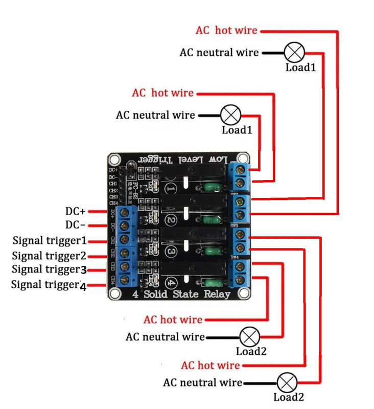
Input:
- DC+: Connect this pin to the positive supply voltage, in accordance with the relay voltage requirement.
- DC-: Connect this pin to the negative supply voltage.
Signal Triggering Terminals (Channels):
- CH1: Use this terminal to trigger the switching action of the relay module for Channel 1.
- CH2: Use this terminal to trigger the switching action of the relay module for Channel 2.
- CH3: Use this terminal to trigger the switching action of the relay module for Channel 3.
- CH4: Use this terminal to trigger the switching action of the relay module for Channel 4.
Output:
- Load 1: Connect the load for Channel 1. This channel supports a load of up to 2 A at 240 VAC.
- Load 2: Connect the load for Channel 2. This channel also supports a load of up to 2 A at 240 VAC.
- Load 3: Connect the load for Channel 3. This channel supports a load of up to 2 A at 240 VAC.
- Load 4: Connect the load for Channel 4. This channel also supports a load of up to 2 A at 240 VAC.
Applications:
- Relay Drive from External Contacts: Using external contacts to trigger the relay module allows integration with external devices or sensors, making it suitable for applications like remote monitoring and control systems.
- LED Series and Parallel Connections: The module can be used to control LED lighting setups, enabling dynamic configurations such as series or parallel connections. This finds applications in decorative lighting, architectural lighting, and customized illumination designs.
- Home Automation: The module's ability to control various loads makes it a cornerstone of home automation systems. It can manage lighting, appliances, HVAC systems, and more, enhancing comfort and energy efficiency.
- High Current Load Switching: With its capability to handle high-current loads, the module is ideal for applications like heavy-duty industrial machinery, high-power appliances, and large-scale lighting systems.
- Electro-Mechanical Relay (EMR) Replacement: The module can replace traditional electromagnetic relays, reducing maintenance and offering faster response times in applications where reliability and precision are paramount.
- Automatic Test Equipment: In testing setups, the module can be employed to switch various components and devices under test, allowing for automated testing procedures with accurate and rapid switching.
- Instrumentation Systems: The precision of the solid-state relay module makes it suitable for use in instrumentation systems, where precise control and low noise are critical for accurate measurements.
- Industrial Automation: From conveyor systems to production lines, the module is well-suited for industrial automation setups, enabling efficient control of machines and processes.
- Thermostats: Integrating the module with thermostat systems can enhance control over heating, cooling, and ventilation equipment, optimizing energy usage and maintaining desired comfort levels.
- Programmable Logic Controllers (PLCs): The module's compatibility with digital control signals makes it an excellent match for PLC-controlled systems, allowing for seamless integration into complex industrial processes.
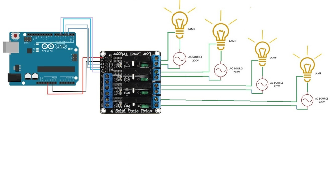
Circuit:
in this example, we will blink a 4 x 220v lamp for 1sec and shoot it down for 1sec
Library:
This Module doesn't need a library to work.
Code:
The code essentially simulates the switching of each channel (relay) on and off sequentially, with a one-second interval between each action. The status information is displayed in the serial monitor, allowing you to monitor the switching process and channel statuses in real-time:
void setup() {
  // Initialize digital pins 2, 3, 4, and 5 as outputs.
  pinMode(2, OUTPUT);
  pinMode(3, OUTPUT);
  pinMode(4, OUTPUT);
  pinMode(5, OUTPUT);

  // Set initial state of all channels to HIGH (off).
  digitalWrite(2, HIGH);
  digitalWrite(3, HIGH);
  digitalWrite(4, HIGH);
  digitalWrite(5, HIGH);

  // Initialize serial communication at 9600 bps.
  Serial.begin(9600);
}

void loop() {
  // Loop through channels 2 to 5.
  for (int channel = 2; channel <= 5; channel++) {
    digitalWrite(channel, LOW);  // Turn the LED on by making the voltage LOW.
    Serial.print("Channel ");
    Serial.print(channel);
    Serial.println(" ON");
    delay(1000);  // Wait for a second.
    digitalWrite(channel, HIGH); // Turn the LED off by making the voltage HIGH.
    Serial.print("Channel ");
    Serial.print(channel);
    Serial.println(" OFF");
    delay(1000);  // Wait for a second.
  }
}
-
In the
setup()function:- The digital pins 2, 3, 4, and 5 are initialized as outputs using the
pinMode()function. - The initial state of all channels is set to HIGH (off) using the
digitalWrite()function, ensuring that the relays start in the off state. - Serial communication is initialized at a baud rate of 9600 bps using the
Serial.begin()function. This allows status information to be sent to and received from the serial monitor.
- The digital pins 2, 3, 4, and 5 are initialized as outputs using the
-
In the
loop()function:- A
forloop is used to iterate through channels 2 to 5. - For each channel, the corresponding pin is set to LOW using
digitalWrite()to turn on the relay (LED), and a status message is sent to the serial monitor indicating that the channel is ON. - The code then waits for a second using the
delay()function. - The channel is turned off by setting the pin to HIGH using
digitalWrite(), and another status message is sent to the serial monitor indicating that the channel is OFF. - Another
delay()of one second follows to create a visible sequence of turning on and off the channels.
- A
Technical Details:
- Supply voltage: 5V DC
- Number of channels: 4
- Quiescent current: 0mA
- Operating Current: 12.5mA
- Trigger mode: high-level trigger
- Load voltage: AC 240V
- Load current: 2A
- Module life: 10 million times
- Switch the maximum frequency: 5KHz
- DC 0 – 2.5V Relay is OFF
- DC 3.3 – 5.0V Relay is ON
Resources:
Comparisons:
This comparison highlights the fundamental differences between EMRs and SSRs, showcasing their respective strengths and weaknesses in various applications:
Electro-Mechanical Relays (EMRs):
- Utilize coils, magnetic fields, springs, and mechanical contacts for operation.
- Switch supply by physically manipulating components.
- Have moving parts that can wear out over time.
- Provide input-to-output isolation through mechanical design.
- Suitable for both AC and DC load switching.
- Can handle higher current loads.
- Emit audible clicking sound when switching.
- Relatively larger in size.
- More susceptible to arcing and sparking.
Solid-State Relays (SSRs):
- Employ solid-state semiconductors for operation.
- Execute switching actions through electrical and optical properties.
- Lack of moving parts, leading to a longer operational lifespan.
- Achieve input-to-output isolation using electrical and optical properties.
- Primarily designed for AC load switching.
- Handle lower current loads compared to EMRs.
- Operate silently without mechanical clicking.
- Compact in size due to the absence of moving components.
- Minimize wear, arcing, and sparking concerns.
you can check this item if you want more current.