A solid state relay (SSR) isintegrated circuit that functions like a mechanical relay. it enable you to control high-voltage ACloads usingDC Voltagecontrol circuitry. it accomplish this usinginfrared light as the 'contact,and a solid-state relay is just an Infrared LED and a photo-triac sealed up in a small package.
AED 4.95
Description
The Solid-State Relay provides a modern and efficient solution for controlling high-voltage AC loads using low-voltage DC control signals. With its reliable semiconductor technology and impressive performance, it offers a compelling alternative to traditional mechanical relays in various electronic and industrial applications.
Note: This SSR switches one channel of 100-240VAC at up to 2A. The SSR can turn to switch AC ON or OFF, but it cannot be used for dimming. it also cannot be used to switch DC voltages.
Package Includes:
- 1 x Relay Solid State SSR DC 5V to AC 100-240V 2A
Features:
-
Output Rating: The G3MB-202P SSR is capable of switching a single channel of AC load with a voltage range of 100VAC to 240VAC.
- Output Current: The SSR can handle a maximum load current of 2 Amperes (2A).
- SPST-NO Configuration: It is a Single-Pole, Single-Throw Normally Open (SPST-NO) type relay, meaning it can either allow current to flow through the output when activated or stop the current flow when deactivated.
- Compact Design: The G3MB-202P comes in a small and compact package, making it suitable for applications with limited space.
- Zero Cross Turn-On: This SSR utilizes a zero-crossing turn-on method, which means it switches ON the output load at the point where the AC voltage waveform crosses zero volts. This minimizes voltage spikes and reduces electromagnetic interference (EMI).
- Optically Isolated: The input and output sides of the SSR are optically isolated, providing enhanced safety and protection for the control circuitry.
- Low Input Power Consumption: SSRs have low power consumption in the input circuit, making them energy-efficient and suitable for battery-operated devices.
- Long Service Life: The absence of mechanical parts in SSRs contributes to their extended service life, as there is no wear and tear from mechanical switching.
- Fast Switching Speed: Solid-state relays can switch at high speeds, allowing for rapid response times in various applications.
Description:
A Solid-State Relay (SSR) is an advanced electronic component designed to perform a similar function to that of a traditional mechanical relay but with several significant advantages. Unlike mechanical relays, which use moving parts to switch electrical signals, SSRs utilize semiconductor technology to achieve seamless and reliable switching operations. The primary function of an SSR is to control high-voltage AC loads using low-voltage DC control circuitry. It achieves this by employing an innovative method that involves the utilization of infrared light as the "contact." Inside an SSR, you'll find an Infrared Light Emitting Diode (LED) and a photo-Triac enclosed within a compact and robust package. The advantages of using an SSR over a mechanical relay are manifold. SSRs offer superior reliability due to the absence of moving parts, making them virtually maintenance-free and highly durable. Additionally, they exhibit faster response times, minimizing switching delays and improving overall system efficiency. It's important to note that the SSR discussed here is specifically designed to switch one channel of 100-240VAC at up to 2A. This means it is capable of turning AC loads ON or OFF with ease. However, it's crucial to understand that this particular SSR is not suitable for dimming applications, nor can it be used to switch DC voltages.
Principle of Work:
The Solid-State Relay (SSR) consists of several key components that enable it to function as an electronic switching device without any moving parts. The main components of an SSR are:
- Infrared Light Emitting Diode (LED): The input side of the SSR contains an Infrared LED. When a low-voltage DC control signal is applied to the input terminals, the LED emits infrared light.
- Photo-Triac or Photo-SCR: The output side of the SSR contains a semiconductor device known as a Photo-Triac or Photo-SCR (Silicon Controlled Rectifier). This component is optically coupled to the Infrared LED.
The working principle of an SSR is as follows:
- Control Signal Input: To operate the SSR, you need to apply a low-voltage DC control signal to the input terminals. This control signal typically comes from a microcontroller or MCU (Microcontroller Unit).
- Infrared Emission: When the control signal is applied, the Infrared LED on the input side of the SSR is activated, emitting infrared light.
- Optical Coupling: The emitted infrared light from the Infrared LED reaches the output side of the SSR and falls onto the surface of the Photo-Triac or Photo-SCR. This forms an optical coupling between the input and output sides of the SSR.
- Switching Action: When the Photo-Triac or Photo-SCR receives the infrared light, it becomes conductive, allowing current to flow through the output circuit. As a result, the SSR effectively acts as a switch, allowing the passage of current from the high-voltage AC load connected on the output side.
- Isolation: The key advantage of SSRs is their electrical isolation between the input and output sides. There is no physical connection between the control circuitry (microcontroller) and the high-voltage AC load, providing improved safety and protection for the control circuit.
To make the SSR work with an MCU, you need the following components:
- Microcontroller: An MCU, such as Arduino, Raspberry Pi, or any other suitable microcontroller board, to generate the low-voltage DC control signal.
- Solid-State Relay (SSR): Choose an appropriate SSR that matches the voltage and current requirements of your load. Ensure it has an Infrared LED and a suitable Photo-Triac or Photo-SCR.
- Power Supply: Provide the required power supply for both the microcontroller and the SSR. The microcontroller typically requires a lower DC voltage, while the SSR needs a voltage suitable for the load it will control.
- Signal Conditioning (Optional): Depending on the microcontroller's output signal level and the SSR's input requirements, you may need to use signal conditioning components, such as transistors or optocouplers, to interface the MCU with the SSR effectively.
- Load: Connect the high-voltage AC load that you want to control (e.g., lights, heaters, motors) to the output terminals of the SSR.
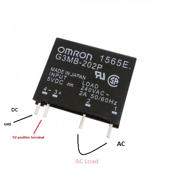
Pinout of the Module:
|
Pin Number/Type |
Pin Description |
|
1 |
Load |
|
2 |
Load |
|
3(+) |
5V positive terminal |
|
4(-) |
Ground |
Applications:
- Home Automation: The SSR can be used in home automation systems to control appliances like lights, fans, and heaters. It allows for efficient and reliable switching of AC loads based on user commands or sensor inputs.
- Industrial Control: In industrial automation, the G3MB-202P SSR can be employed to switch AC loads in machinery, pumps, motors, and other equipment. Its compact design and fast switching speed make it suitable for control panels.
- Temperature Control: The SSR can be utilized in temperature control systems to turn heating elements ON and OFF in devices like ovens, incubators, and industrial furnaces.
- Power Management: The SSR is useful in power management systems, allowing for precise control of AC power distribution in various circuits.
- Lighting Control: The SSR can be used to switch lighting systems, such as streetlights, indoor lighting, and stage lighting, providing efficient and reliable control.
- HVAC Systems: The G3MB-202P SSR can be integrated into heating, ventilation, and air conditioning (HVAC) systems to control fans, blowers, and heating elements.
- Home Security: In security systems, the SSR can be employed to activate alarms, sirens, or warning indicators when motion sensors or other security sensors are triggered.
- Photovoltaic (PV) Systems: The SSR can be used in PV systems to control the connection of solar panels to the grid or to battery storage.
- Medical Equipment: The SSR can be found in medical devices and equipment where precise and reliable switching of AC loads is necessary.
- Food Processing: In food processing equipment, the SSR can control heating elements in ovens, toasters, and other cooking appliances.
Circuit:
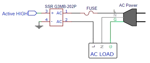
- Connecting the SSR: One side of the SSR (marked with a "+" sign) is connected to Pin 3 of the Arduino. This allows the Arduino to send a low-voltage signal to the SSR to control it.
- Dealing with 220V: Here's the important part - you must be very cautious and careful when connecting the circuit because you are dealing with 220VAC, which can be extremely dangerous. Make sure to follow safety guidelines and avoid touching any live wires while working on the circuit.
- Controlling the Lamp: Once the circuit is set up correctly and safely, you can program the Arduino to send signals to the SSR through Pin 3. When the Arduino sends a signal, the SSR will turn ON, and the lamp connected to the SSR will blink. When the signal stops, the SSR will turn OFF, and the lamp will stop blinking.
Safety Tips:
- Always double-check your connections and ensure they are secure.
- Work on the circuit only when it is disconnected from the power source.
- Avoid touching any exposed wires or components when the circuit is powered.
- If you are unsure about handling high-voltage circuits, seek assistance from someone experienced or a qualified professional.
Remember, safety should be the top priority when dealing with high-voltage circuits, so take all necessary precautions and never take risks when working on such projects.
Library:
This Module doesn't need a library to work.
Code:
void setup() {
  pinMode(3,OUTPUT);
}

void loop() {
  digitalWrite(3,HIGH);   // Load runs for one sec
  delay(1000);
  digitalWrite(3,LOW);    // Load stops for one sec
  delay(1000);
}
Technical Details:
|
Technical |
|
|---|---|
| Current Rating | 2 A |
| Input Current | 50 mA |
| Insulation Resistance | 1 GΩ |
| Isolation Voltage | 2.5 kV |
| Load Current | 2 A |
| Max Operating Temperature | 80 °C |
| Max Output Current | 2 A |
| Max Output Voltage | 264 V |
| Min Operating Temperature | -30 °C |
| Output Current | 2 A |
| Mount | Through Hole |
| Number of Pins | 4 |
| Termination | PC Pin |
| Throw Configuration | SPST |
| Height | 20.6 mm |
| Length | 24.4 mm |
| Width | 5.59 mm |
Resources:
Comparisons:
The choice between the G3MB-202P SSR and the 5V 10A mechanical relay depends on the specific requirements of the application. If you need fast switching, low noise, longer lifespan, and low power consumption, the G3MB-202P SSR is a better choice. On the other hand, if you have a general switching application and do not need ultra-fast switching speeds, the 5V 10A mechanical relay can be a suitable and cost-effective option:
-
Type of Relay:
- G3MB-202P: It is a Solid-State Relay (SSR), which uses semiconductor components for switching and does not have any moving parts.
- 5V 10A Mechanical Relay: It is a traditional electromechanical relay that uses a coil and a set of contacts to switch the load.
-
Switching Speed:
- G3MB-202P: SSRs have faster switching speeds compared to mechanical relays. They can switch ON and OFF in microseconds, making them suitable for applications requiring rapid switching.
- 5V 10A Mechanical Relay: Mechanical relays have slower switching speeds compared to SSRs, typically in the range of milliseconds.
-
Noise and EMI:
- G3MB-202P: SSRs generate less noise and electromagnetic interference (EMI) because they have no moving parts, resulting in quieter operation.
- 5V 10A Mechanical Relay: Mechanical relays may produce audible clicking noise during switching, and their moving contacts can generate some EMI.
-
Contact Wear and Tear:
- G3MB-202P: As an SSR, it has no mechanical contacts, leading to virtually no wear and tear and longer lifespan.
- 5V 10A Mechanical Relay: Mechanical relays have physical contacts that can wear out over time due to mechanical switching, potentially requiring replacement.
-
Driving Voltage:
- G3MB-202P: The G3MB-202P is typically driven by a low-voltage DC signal, such as 5V DC, suitable for microcontrollers like Arduino.
- 5V 10A Mechanical Relay: A mechanical relay usually requires a higher driving voltage (e.g., 5V or 12V) to energize the coil and switch the contacts.
-
Applications:
- G3MB-202P: SSRs are commonly used in applications where fast switching, low noise, and extended lifespan are essential, such as home automation, lighting control, and industrial control systems.
- 5V 10A Mechanical Relay: Mechanical relays are suitable for general switching applications, where the switching speed and noise level are less critical, and the load current is within the relay's capacity.
-
Power Consumption:
- G3MB-202P: SSRs have low power consumption in the input circuit, making them energy-efficient.
- 5V 10A Mechanical Relay: Mechanical relays consume more power due to the energizing of the coil.