AED 26.25
Description
The Arduino Pro Mini ATmega168 Blue is a minimal design of Arduino. it's a 3.3V Arduino running on 8MHz and with a bootloader. it does not come with a USB connector on board nor a Serial Converter so you can solder in any connector or wire as your suit and for lower-Price.
Package Includes:
- 1 x Arduino Pro Mini ATmega168p 3.3V 8MHz Blue (Compatible)
Features:
-
Microcontroller:- ATmega168P
-
Operating Voltage:- 3.3VInput Voltage:- 3.3 - 12 V ( If use 5V, input 5V to Vcc, if used above 5V, input to RAW pin)
-
Digital I/O Pins: *14 Digital pins labeled as RXI, TXO, 2 to 13: (of which 6 provide PWM output, which is pins 3, 5, 6, 9, 10, and 11)
-
*8 Analog Input Pin: (label as A0, A1, A2, A3 and A4, A5, A6, A7)
-
DC Current per I/O Pin allowed 40 mA, but the max total allowed 150mA for the sum of all pins.
- Flash Memory 16 KB (of which 2 KB is used by the bootloader)
SRAM 1 KB
EEPROM 512 bytes
Clock Speed 8MHz - 3.3V regulating circuit
Description:
The Arduino Pro Mini Blue is a minimal design of Arduino. it's a 3.3V Arduino running on 8MHz and with a bootloader. it does not come with a USB connector on board nor a Serial Converter so you can solder in any connector or wire as your suit and for lower-Price. Arduino Pro Mini is quite similar to Arduino UNO in overall functionality however the main difference lies in its size and built-in programmer. Arduino Pro Mini is very small in size & it lacks a built-in programmer & USB Port. This version of Arduino Uno pro mini comes with onboard voltage regulators 5V and extra 2 Analog pins compared to Arduino UNO.
Principle of Work:
Arduino is Free hardware which is anything whose blueprints and specs are available for anybody to copy. This means that Arduino provides the framework so that any other individual or business can design their own boards, each of which can be unique yet function well when built upon the same framework. Free software is a computer program whose source code is available to anybody, allowing them to use and alter it as they see fit. In order to allow anyone to create apps for Arduino boards and provide them with a variety of utilities, Pro Mini works with the Arduino IDE (Integrated Development Environment) platform. which you can use to program and upload your code (sketch) and do this using an External Serial Converter with the help of an embedded bootloader you can easily do this, the Pro Mini uses libraries that can be downloaded online and gives you the ability to program a big number of sensor and module without even knowing how they really work.
Pinout of the Module:

- Digital Pins: Arduino Pro Mini has 14 Digital I/O Pins in total labeled from 0 to 13, where Pin 0 is RX1 and Pin 1 is TX0.
- Analog Pins: The SMD Atmel 168p chip on this board has 8 channel ADC which can be used for interfacing 8 different analog sensors at the same time. Furthermore, the Analog input Pin A4 and A5 can also be utilized for the I2C communication protocol. Additionally, the first 6 Analog pins can be used as interrupts.
- Arduino Pro Mini supports 3 Communication Protocols for the transmission of data with other peripherals i.e. sensors, registers, etc., and is named:
- Serial Protocol.
- I2C Protocol.
- SPI(Serial Peripheral Interface) Protocol.
- TXD & RXD Pins: These pins are used for serial communication. TXD represents serial data transmission while RXD is used for receiving the data. Code is also uploaded through Serial Protocol.
- SPI Pins: Four pins 10(SS), 11(MOSI), 12(MISO), and 13(SCK) are used for communicating through SPI Protocol.
- I2C Pins: Two Pins(A4 and A5) are used for developing I2C communication. A4 is known as the serial data line (SDA) which holds the data and A5 shows the serial clock line (SCL) which provides a data synchronization clock.
- PWM. There are 6 digital pins labeled 3,5,6,9,10, and 11 available on the board that provide PWM (pulse width modulation).
- External Interrupts. There are two external interrupts available called T0(at Pin 4) and T1(at Pin 5). They are also known as hardware interrupts.
Applications:
- Traffic Light Count Down Timer.
- IoT Systems.
- Parking Lot Counter.
- Embedded systems.
- Home Automation.
- Industrial Automation.
- Medical Instrument.
- Emergency Light for Railways.
Circuit:
We will not need any circuit, in this testing code, we will rely on the built-in LED on the 13th pin.
Connecting with Arduino First Time
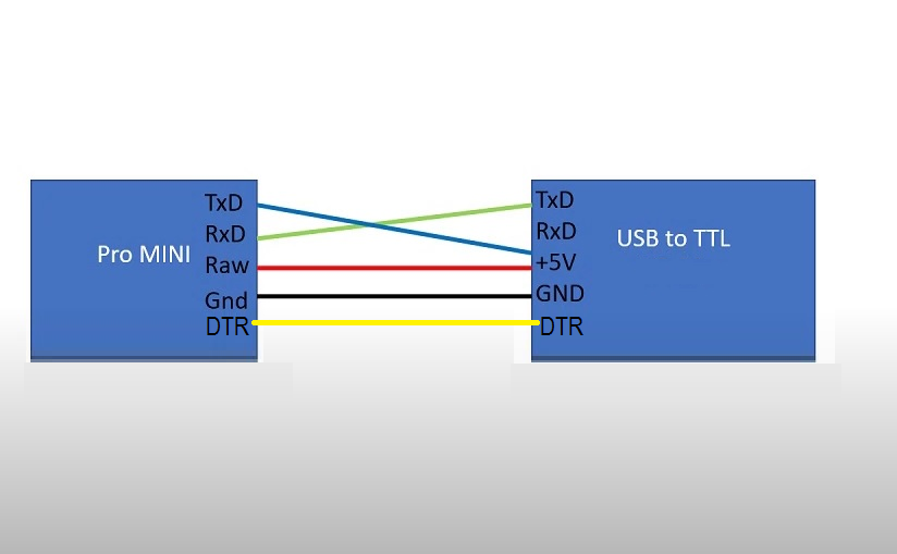
Choose your connection method for the FTDI Basic Breakout and the Pro Mini's programming header first. The programming header is a row of four pins with the labels "GND," "VCC," "RXI," and "TXO,","DTR" on the side of the board. you need to connect it using female-to-female Dupont or as it fits.
If this is the first time that you have plugged the FTDI converter into your computer, you may need to install drivers for it. Check out our Installing FTDI Drivers tutorial for help there as suggested earlier in the tutorial.
-
First, we need to download the Arduino IDE, which can be done from the software page.
-
Install the Arduino IDE on your local machine.
-
Open the Arduino IDE.
Go to Tools > Board and select Arduino Pro or Pro Mini.
Then, go back up to Tools > Processor and select ATmega168(5V, 8MHz).
Selecting the port
Now, let's ensure that our board is found by our computer, by selecting the port. Regardless of what kind of program we are uploading to the board, we always need to choose the port for the board we are using. This is simply done by navigating to Tools > Port, where you select your board from the list.
This will look different depending on what kind of converter you will use.
Uploading a simple example
You are now ready to start using your board! The easiest way to check that everything is working is to upload just a simple blink example to your board. This is done by navigating to File > Examples > 01.Basics > Blink. or the code next
To upload the sketch, simply click on the arrow in the top left corner. This process takes a few seconds, and you will see compiling code is visible in the bottom left corner.
"Done uploading."
Now you will see the onboard LED connected to pin 13 Blinking.
Code:
void setup() {
pinMode(13,1);
}
void loop() {
digitalWrite(13,1);
delay(1000);
digitalWrite(13,0);
delay(1000);
}
Technical Details:
- ATmega168working at 8MHz
- Max 200mA output
- 3.3-12V DC input
- ATmega168P running at 8MHz with external resonator (0.5% tolerance)
- PCB Thin: 0.8mm
- PCB Size in: mm
- Length: 33mm
- Width: 18mm
- Height: 3.5mm
Resources:
- You might also want to look at: the reference for the Arduino language.
- Getting Started Tutorial
- GitHub
Comparisons:
The Arduino Pro Mini and the Arduino Pro Mini ATmega168p 3.3V 8MHz Blue (compatible clone) are similar in terms of their digital I/O pin layout, with 14 digital pins labeled as RXI, TXO, 2 to 13, and 6 of them providing PWM output. Both boards also have 8 analog input pins labeled as A0 to A7. Both boards also have the same DC current per I/O pin, at 40 mA, with a maximum total of 150 mA for the sum of all pins. there are some key differences between the two boards. The main difference is that the compatible clone operates at a voltage of 3.3V, while the original Arduino Pro Mini operates at 5V. This means that the compatible clone can be used with devices that run at 3.3V, while the original Arduino Pro Mini cannot. The compatible clone also has a smaller amount of flash memory, at 16KB (of which 2KB is used by the bootloader) compared to 32KB in the original Arduino Pro Mini. Similarly, the SRAM and EEPROM are also smaller at 1KB and 512 bytes respectively, compared to 2KByte and 1KByte in the original Arduino Pro Mini. Additionally, the compatible clone has a clock speed of 8MHz, which is half that of the original Arduino Pro Mini's clock speed of 16 MHz. The compatible clone also has a 3.3V regulating circuit and allows input voltage between 3.3V to 12V, where you can use 5V to Vcc and above 5V to RAW pin. the Arduino Pro Mini ATmega168p 3.3V 8MHz Blue (compatible clone) is similar to the original Arduino Pro Mini, but operates at a lower voltage and has a smaller memory capacity and clock speed. This makes it more suitable for devices that run at 3.3V and low-power applications. It is important to note that the pinout and functionality of the boards are the same, but you may have slight differences in the physical layout and silkscreen labeling. Some compatible clones may have slight variations in the physical layout and silkscreen labeling, but the pinout and functionality should be the same..