AED 5.25
Description
SW-420 tilt sensor module with an adjustable trimpot and a comparator chip to provide an adjustable digital output based on the amount of vibration. The sensitivity can be increased or decreased by adjusting the multiturn trimpot. In addition, two onboard indicators declare the power and trigger/output status. The module's operating voltage ranges from 3.3V to 5V DC.
Package Includes:
- 1 x Tilt Shock Sensor Module LM393
Features:
- Advanced Vibration Sensing: The SW-420 vibration sensor is a normally closed type, ensuring precise detection capabilities for a wide range of vibration intensities.
- High-Performance Comparator: Equipped with an LM393 wide voltage comparator, the device's comparator output delivers a clean signal with excellent waveform quality. It boasts a robust driving ability, supporting currents of over 15 mA for reliable and efficient operation.
- Versatile Digital Output: The output format is in the form of a digital switch output, providing clear binary signals (0 and 1) for seamless integration into digital systems.
- Intuitive Result Display: Featuring an on-board indicator LED, the sensor visually communicates results, enhancing user awareness of vibration events and ensuring quick and easy interpretation of sensor data.
- Convenient Installation: Designed with a fixed bolt hole, the sensor facilitates straightforward and hassle-free installation, making it ideal for various applications where quick setup is essential.
Description:
SW-420 tilt sensor module with an adjustable trimpot and a comparator chip to provide an adjustable digital output based on the amount of vibration. The sensitivity can be increased or decreased by adjusting the multiturn trimpot. In addition, two onboard indicators declare the power and trigger/output status. The module's operating voltage ranges from 3.3V to 5V DC When no vibration or tilt, the product is ON conduction state, and in the steady state, when vibration or tilt, the switch will be rendered instantly disconnected the conductive resistance increases, generating an current pulse signal, thereby triggering the circuit. the module can be used for toys, gadgets, and appliances. They are also known as" "tilt switches," or "rolling ball sensors" for obvious reasons.
Principle of Work:
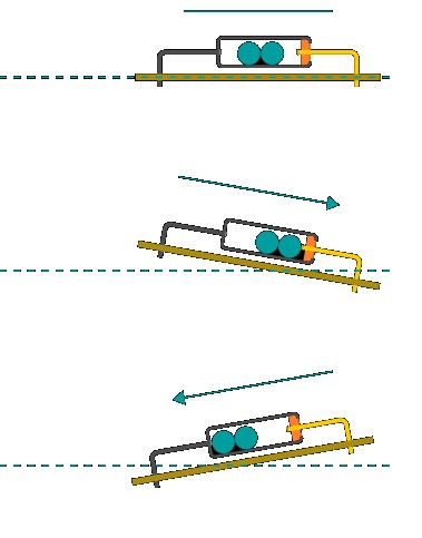
The SW-420 Tilt Sensor is a versatile device designed for dual functionality, capable of serving both as a tilt sensor for horizontal positioning and as a vibration sensor for vertical positioning. This sensor comprises two internal balls, enhancing its sensitivity to changes in orientation. In terms of vibration detection, the module actively responds to external impulses and vibrations, producing logic-level outputs. Specifically, when there is no vibration, the output remains in the logic-low (L) state. However, during the detection of vibrations, the output momentarily switches to the logic-high (H) level. For additional insights, it's crucial to understand that the sensor functions as an on/off switch, determined by its alignment in relation to the horizontal design plane. To utilize the tilt function, inclining the sensor beyond 15 degrees from the horizontal position is necessary. If the inclination is towards the conductor terminal side (A), the circuit opens, indicating the off state. Conversely, if the inclination is 15 degrees from the opposite side, towards terminal (C), the circuit closes, indicating the on state. This dual-mode operation adds a layer of versatility to the sensor, making it adaptable to specific orientation-dependent applications.
Pinout of the Module:

|
Pin |
Description |
|
VCC |
The Vcc pin powers the module, typically with +5V. It serves as the primary source of electrical energy for the proper functioning of the sensor module. |
|
GND |
Power Supply Ground. This pin establishes the electrical reference point, completing the circuit and ensuring proper power distribution. |
|
DO |
Digital Out Pin for Digital Output. The DO pin produces a digital output signal, indicating the status or measurement provided by the sensor module. This signal is ready for integration into digital systems. |
- LM393 IC
In this vibration sensor module, an LM393 Comparator IC is employed as a voltage comparator. Pin 2 of the LM393 is wired to the Preset (10K Pot), while Pin 3 is wired to the vibration sensor. The comparator IC will compare the preset (pin 2) threshold voltage and the Vibration Sensor pin. - Preset (Trimmer pot)
You can change the threshold (sensitivity) of the digital output using the onboard preset. - Vibration Switch SW-420
The amplitude of the vibration to which it is exposed is recognized by the vibration switch. The switch response might be either an electrical contact closure or an electrical contact opening. An electromechanical relay or a solid-state device can serve as the electrical contact.
Applications:
- Security Systems: Used to detect unauthorized movement or tampering, the sensor is integrated into security systems to trigger alarms or alert systems in the event of vibration or tilt.
- Industrial Machinery Monitoring: Employed in industrial settings to monitor the vibration levels of machinery, helping in preventive maintenance and early detection of potential faults.
- Automotive Security: Integrated into car security systems to detect unauthorized attempts to move or tamper with the vehicle, triggering anti-theft measures.
- Home Automation: Incorporated in smart home applications to monitor the orientation of doors and windows. It can trigger alerts or automate actions based on changes in position.
- Robotics: Integrated into robots to detect changes in their orientation, enabling them to navigate and adjust their movements based on environmental conditions.
- Consumer Electronics: Incorporated in electronic devices like smartphones and cameras to enable features such as auto-rotation of the screen or image stabilization.
- IoT (Internet of Things) Projects: Integrated into various IoT applications for position sensing, where the sensor's output can be used to control or trigger actions in smart environments.
Circuit:
The D13 pin serves as the connection point for the LED within the module, providing a visual indicator. Power for the module is sourced from the Arduino's 5V pin, ensuring a stable supply. In this configuration, the Arduino is effectively powered through its Ground and 5V pins. Furthermore, the A5 pin on the Arduino is designated for retrieving data from the vibration sensor. By connecting to the A5 pin, the Arduino can receive and process the analog signals generated by the vibration sensor module, facilitating the incorporation of vibration-related data into the broader functionality of the Arduino-based system. This comprehensive setup allows for both power supply and data communication, enabling seamless integration of the vibration sensor module with the Arduino platform.

Library:
No Library is needed for this module to function
Code:
The LED, connected to Pin 13 on the Arduino UNO, functions as an observable indicator when the vibration sensor is activated or undergoes a status change. Specifically, in the presence of vibrations, the LED linked to Arduino UNO Pin 13 will exhibit a blinking pattern, providing a visual representation of the sensor's response. Should the vibration sensor not exhibit expected behavior, it is recommended to verify the integrity of the connections and power supply. Ensuring a secure and reliable connection between the sensor and the microcontroller is crucial for optimal functionality.
#include "stdio.h"
#define ON 1
#define OFF 0


int vibration_Sensor = A5;
int LED = 13;
int present_condition = 0;
int previous_condition = 0;


void setup() {
  pinMode(vibration_Sensor, INPUT);
  pinMode(LED, OUTPUT);

}


void led_blink(void);
void loop() {

  previous_condition = present_condition;
  present_condition = digitalRead(A5); // Reading digital data from the A5 Pin of the Arduino.

  if (previous_condition != present_condition) {
    led_blink();
  } else {
    digitalWrite(LED, OFF);
  }

}

void led_blink(void) {
  digitalWrite(LED, ON);
  delay(250);
  digitalWrite(LED, OFF);
  delay(250);
  digitalWrite(LED, ON);
  delay(250);
  digitalWrite(LED, OFF);
  delay(250);
}
Technical Details:
- Current: ~ 30mA
- The working voltage of 3.3V to 5V
- Small board PCB size: 3.2cm x 1.4cm
- Conductive time: About 1s
- Closed resistance: 0-200 ohm
- Open resistance: >10M ohm
- Temperature range: -40 to 80℃
- Pull force of terminal: 500gf for 1 minute
- Humidity: 95% RH, 40℃ for 96 hours
- Operating lifespan: above 1000000 circle
Resources:
Comparisons:
Switch-Based Tilt Sensors operate by determining whether the system is tilted or not, featuring a basic two-output state design. These sensors fall into two main categories:
-
Ball in a Cage Structure Switches: Switches within this category incorporate a metallic ball enclosed in a cage. The design is crucial, necessitating a stress and vibration-resistant metal ball. Opting for a solid and thick structure, as opposed to a hollow one, ensures durability and reliability in various conditions.
-
Mercury Tilt Switch: This type relies on a mercury bead that bridges the switch's terminals when tilted. Mercury tilt switches, one of the earliest varieties, exhibit a slower response time. They are available in Single Pole Single Throw (SPST) and Single Pole Double Throw (SPDT) variations based on the number of contacts used.
Mercury, functioning as a liquid metal, flows to establish contact between the switch's leads during tilting. While effective, the use of mercury is discouraged due to its toxicity. In the event of a glass casing breakage and metal spillage, there's a potential hazard to the user. Alternative designs and materials are encouraged to ensure safety and environmental sustainability.