AED 9.45
Description
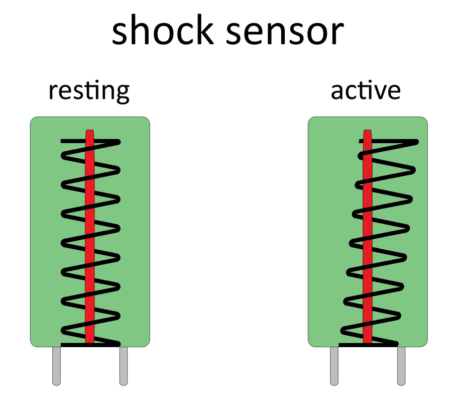
The KY-002 Vibration Switch Module has an SW-18015P shock and vibration sensor. It is made up of a conductive outer shell that makes touch with an interior spring in the event of a shock. Closing the contact is analogous to hitting a button.
The sensor is connected to a resistor that serves as a pull-up resistor. This means that the sensor module can be directly linked to a digital signal input without the need for any additional components.
Package Includes:
- 1 x Tilt Shock Sensor Module Ky-002
Features:
- This kind of switch is safer than mercury switches and has the same characteristics as the wizard rock single pass but the assembly is more convenient
- Made of environmentally friendly raw material
- The module is easy to interface with microcontrollers.
- Cheap and reliable
- It has a great durability rate.
Description:
The Tilt Shock Sensor Module Ky-002 detects when the module has been tilted. The shock sensor SW11810P, also known as a vibration sensor or shake sensor, can be used in a variety of applications. For example, you can use it to wake up a system when you shake it, or you can use it in a toy to make noise when you shake it, or you can use it in a security system.
Principle of Work:
Inside the sensor is a thin metal wire spring wrapped around a metal conductive leg, and the outer shell wraps around all of this. The metal conductive wire is linked to five volts, and a springy wire is wrapped around the solid wire. When there is a vibration, the spring will strike the solid, and the five volts will pass through the spring, and the Arduino will read the difference in voltage and provide our signal. If we shake the sensor, the thin metal spring and the metal conducting leg will come into contact with each other, and electricity will flow from the metal conductive leg to the thin metal wire spring. We will then have a 5-volt potential and will be able to detect a shaking or vibration. This component on the module is the shock sensor, which has the shape of a cylindrical capacitor and a 10-kilo ohm resistor.
Pinout of the Module:
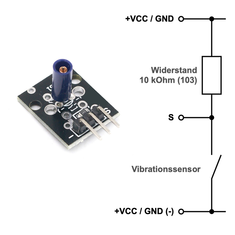
(-): ground (GND) and zero volts
Right (S): The voltage divider's connection point
(+) VCC: 3.3 or 5 volts
Applications:
- Robotics makes extensive use of it.
- It can also be applied to automobiles.
- to determine the direction.
- to be aware of the desire.
Circuit:
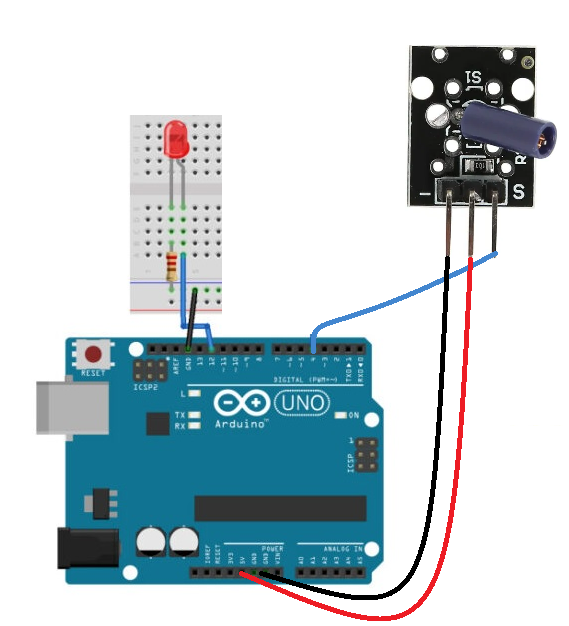
Assemble the Tilt Sensor using the Arduino UNO by connecting an LED to pin 12 with a 220ohm resistor and connecting the sensor S to pin 4 and - to GND and + to VCC5v. Now, copy and paste the code into your Arduino IDE. The code is then uploaded to Arduino. To see the glowing LED, tilt and move the sensor.
Library:
No Library is needed for this module to function
Code:
The input sensor pin and output LED pin that are connected to the Arduino pins has been defined. Then, by declaring the variable LastTiltState, we have shown that the sensor's previous stage was high. Next, we must specify the variables debounceDelay and lastdebounce time.
We have specified the sensor pin as the Arduino's input in the void setup. Led is also an output. Additionally, we initialized the serial monitor there.
We have defined the function digitalRead() in the void loop to examine the sensor reading. The sensor will reset the debouncing time if it detects a value identical to the previous lastTiltState stated above, as long as the requirement is met.
additionally returns the millisecond's value. The condition has been created since then. The lastTiltState becomes the sensorValue if the condition is verified. The lastTiltState is also taken by the LED pin. To display the sensor value on the serial monitor, use the Serial. println command.
int ledPin = 12;
int sensorPin = 4;
int sensorValue;
int lastTiltState = HIGH;   // the previous reading from the tilt sensor

// the following variables are long's because the time, measured in miliseconds,
// will quickly become a bigger number than can be stored in an int.
long lastDebounceTime = 0;  // the last time the output pin was toggled
long debounceDelay = 50;    // the debounce time; increase if the output flickers

void setup(){
  pinMode(sensorPin, INPUT);
  digitalWrite(sensorPin, HIGH);
  pinMode(ledPin, OUTPUT);
  Serial.begin(9600);
}

void loop(){
  sensorValue = digitalRead(sensorPin);
  // If the switch changed, due to noise or pressing:
  if (sensorValue == lastTiltState) {
    // reset the debouncing timer
    lastDebounceTime = millis();
  }
  if ((millis() - lastDebounceTime) > debounceDelay) {
    // whatever the reading is at, it's been there for longer
    // than the debounce delay, so take it as the actual current state:
    lastTiltState = sensorValue;
  }
  digitalWrite(ledPin, lastTiltState);

  Serial.println(sensorValue);
  delay(500);
}
Technical Details:
- Max Current: 30mA
- Max voltage: 5V
- Insulation Resistance:>10M ohm
- Dimensions: (1.8 x 1.5 x 0.9cm)
Resources:
- Tutorial
- Raspberry Pi Pico: Program pedometer with Vibration Sensor KY-002
- Raspberry Pi Pico: Programming a shock detector with Vibration Sensor KY-002
- Raspberry Pi Pico: Programming theft alarm with buzzer and vibration sensor KY-002
Comparisons: