AED 38.00
Description
- The Color Recognition Sensor Module TCS3200 White PCB is a sensor that can detect colors and provide a readout of individual RGB color components as a digital frequency. It uses a TAOS TCS3200 RGB sensor chip to detect color and contains four white LEDs that light up the object in front of it.
- The sensor has an array of photodiodes with four different filters, and a photodiode is a semiconductor device that converts light into current. The sensor can be connected directly with a microcontroller and can be used for color recognition projects such as color matching, color sorting, and test strip reading. The sensor can detect non-luminous object color and has anti-light interference.
Principle of Work:
- White light is made up of three primary colors (Red, green and blue), which have different wavelengths. These colors combine with each other to form different shades of colors.
- When white light falls on any surface, some wavelengths of light are absorbed and some are reflected, depending on the properties of the surface material. The color we see is a result of which wavelengths are reflected back into our eyes.
- Now coming back to the sensor, a typical color sensor includes a high-intensity white LED that projects a modulated light onto the object. To detect the color of reflected light, almost all the color sensors consists of a grid of color-sensitive filter, also known as ‘Bayer Filter‘ and an array of photodiodes underneath
- A single pixel is made up of 4 filters, one red, one blue, one green and one clear filter (no filter). This pattern is also known as the ‘Bayer Pattern‘. Each filter passes light of just a single color to the photodiode beneath, while the clear filter passes light as it is, as shown below. This extra light passed through the clear filter is a major advantage in low light conditions.
- The processing chip then addresses each photodiode (one color at a time), and measures the intensity of the light. As there is an array of photodiodes, the results are first averaged and then sent out for processing. By measuring the relative level of red, green and blue light, the color of the object is determined. If you look closely at the sensor, you can actually see these filters.
Features:
- High-Resolution Conversion of Light Intensity to Frequency
- Programmable Color and Full-Scale Output Frequency
- Power Down Feature
- Communicates Directly to Microcontroller/Arduino
- TCS3200 is an upgraded version of TCS230
- Nonlinearity Error Typically 0.2% at 50 kHz
- Stable 200 ppm/°C Temperature Coefficient
- Low-Profile Lead (Pb) Free and RoHS Compliant Surface-Mount Package
- Optimum Distance to Detected Object around 1cm
Specification:
- Power Supply: 3.3 or 5V
- Operating Voltage: 2.7 ~ 5.5V
- Distance Range: 10 to 15mm
- Dimension: 24 x 28.5mm
- Weight: 4.17g
Applications:
- Test strip reading: The TCS3200 can be used to read the color of test strips in medical, chemical, or environmental applications.
- Color sorting: The sensor can be used to sort objects by color, such as in manufacturing processes.
- Ambient light sensing and calibration: The TCS3200 can be used to sense ambient light levels and calibrate displays accordingly.
- Color matching: The sensor can be used in applications such as paint matching or color matching in textiles.
- Industrial automation: The TCS3200 can be used in various industrial automation applications such as quality control, process monitoring, and sorting.
- Robotics: The TCS3200 can be used in robotics to detect and differentiate colors, for example in color-based line following.
- Educational experiments: The sensor can be used in educational experiments to teach concepts such as light, color, and sensing technologies.
Pin Connections:
- Header one on the left side of the board
| Pin | Description |
|---|---|
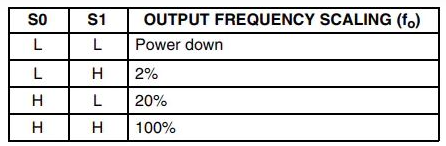
| S0 and S1 | The S0 and S1 pins can be used to select the Output Frequency Scaling Percentage of the sensor. By configuring these pins, it can be set to 2%, 20%, or 100% scaling. |
| LED | LED Control |
| GND | This is the ground pin of the Color Sensor module and should be connected to the ground pin of the Arduino. |
- Header two on the right side of the board
| Pin | Description |
|---|---|
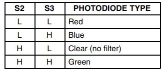
| S2 and S3 | The S2 & S3 pins can be used to select the color array of the sensor. By selecting the right color array one after the other, this sensor identifies a color. |
| OUT | This is the output pin of the sensor. When a particular color is detected by the sensor, the output pulse frequency on this pin changes. By detecting this change in pulse width, we can determine the color. |
| VCC | This is the power supply pin of the color sensor that can be connected to 5V or 3.3V of the supply. |
Package Includes:
- 1 x Color Recognition Sensor Module TCS3200 White PCB
Sample Project:
Circuit:
Now that we have completely understood how a TCS3200 color Sensor works, we can connect all the required wires to Arduino and write the code to get all the data out from the sensor. The Connection Diagram of the TCS3200 with Arduino is shown below:
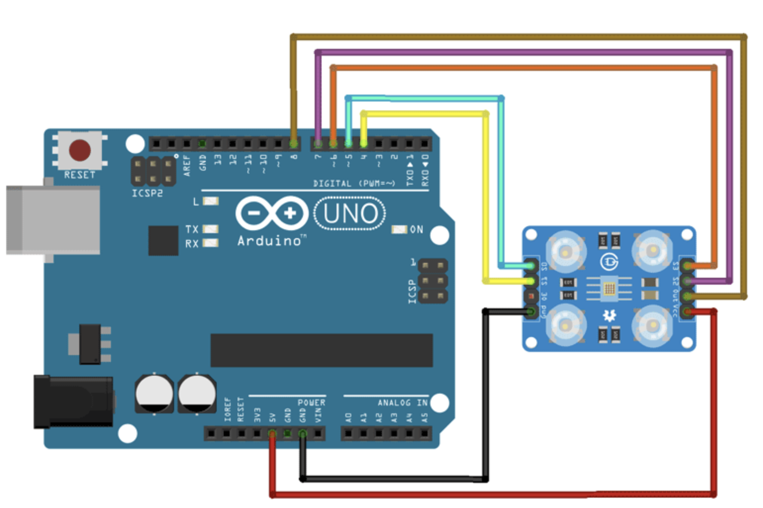
Connecting the TCS3200 sensor with the Arduino is very simple. To communicate with the sensor we don't need anything other than five GPIO pins of the Arduino, and that is why we have used GPIO 8,7,6,5,4 pins of the Arduino. Finally, to power the sensor we have used the 5V and Ground pins of the Arduino Board.
Library:
- No external library is required for this module to w ork.
Code:
/*
    Sensor Pin S0 -> Arduino Pin D8
    Sensor Pin S1 -> Arduino Pin D7
    Sensor Pin S2 -> Arduino Pin D6
    Sensor Pin S3 -> Arduino Pin D5
    Sensor Pin OUT -> Arduino Pin D4
*/
#define S0_PIN 5
#define S1_PIN 4
#define S2_PIN 7
#define S3_PIN 6
#define OUT_PIN  8
void setup()
{
    // Set the S0, S1, S2, S3 Pins as Output
    pinMode(S0_PIN, OUTPUT);
    pinMode(S1_PIN, OUTPUT);
    pinMode(S2_PIN, OUTPUT);
    pinMode(S3_PIN, OUTPUT);
    //Set OUT_PIN as Input
    pinMode(OUT_PIN, INPUT);
    // Set Pulse Width scaling to 20%
    digitalWrite(S0_PIN, HIGH);
    digitalWrite(S1_PIN, LOW);
    // Enabl UART for Debugging
    Serial.begin(9600);
}
void loop()
{
    int r, g, b;
    r = process_red_value();
    delay(200);
    g = process_green_value();
    delay(200);
    b = process_blue_value();
    delay(200);
    Serial.print("r = ");
    Serial.print(r);
    Serial.print(" ");
    Serial.print("g = ");
    Serial.print(g);
    Serial.print(" ");
    Serial.print("b = ");
    Serial.print(b);
    Serial.print(" ");
    Serial.println();
    if (r < 42)
    {
        Serial.println("Colour Pink");
    }
    else if (g < 63)
    {
        Serial.println("Colour Green");
    }
    else if (r < 64)
    {
        Serial.println("Colour Red");
    }
}
int process_red_value()
{
    digitalWrite(S2_PIN, LOW);
    digitalWrite(S3_PIN, LOW);
    int pulse_length = pulseIn(OUT_PIN, LOW);
    return pulse_length;
}
int process_green_value()
{
    digitalWrite(S2_PIN, HIGH);
    digitalWrite(S3_PIN, HIGH);
    int pulse_length = pulseIn(OUT_PIN, LOW);
    return pulse_length;
}
int process_blue_value()
{
    digitalWrite(S2_PIN, LOW);
    digitalWrite(S3_PIN, HIGH);
    int pulse_length = pulseIn(OUT_PIN, LOW);
    return pulse_length;
}
Troubleshooting:
TCS3200 Color Sensor not Working? Here is what you should do:
- If you are having trouble reading the TCS3200 sensor, please first check the operating voltage of the device. The stable operating voltage of this device is 2.7V to 5.5V. Driving the sensor with any other voltage values will make the sensor unstable.
- If you are having fluctuations in the reading try covering up the sensor with a box. This will keep the distance of the sensor constant and also it will reduce the outside noise.
- If you are having scaling issues, please check the S0 and S1 pins of the sensor if they are configured correctly.
- If you are having issues with the output, please make sure that the S2 and S3 pins are configured properly.
Commonly Asked Questions about Color Sensor TCS3200
1. What does a color sensor detect?
A color sensor can detect the received light intensity for red, blue, and green respectively, making it possible to determine the color of the target object.
2. How many pins are there in the color sensor?
It consists of color filters, photodiode array, current to frequency converter and final square wave output which can be given directly to a microcontroller. The TSC3200 Color Sensor IC is an 8 pin IC with SoC(System on a Chip) package. The following image shows the pin diagram of the Colou Sensor IC.
3. Do color sensors work in the dark?
Yes, it can work in the dark because it has four white bright LEDs. The color sensor can distinguish between colors or measure the intensity of the reflected light, making it ideal for line following. By emitting its own light, the sensor can work even in absolute darkness to determine the color or brightness of the surface.
4. What are the main parts of a color sensor?
Color sensors contain a white light emitter to illuminate the surface. Three filters with wavelength sensitivities at 580 nm, 540 nm, and 450nm to measure the wavelengths of red, green and blue colors respectively.
Notes:
- There exists much colour aberration during module testing, so if you have any special need for color testing, pay attention to it.
Pins S0 and S1 are used for scaling the output frequency. Take a look at the table below.
Pins S2 and S3 are used to select one of the 4 photodiode types. Take a look at the table below.
References:
- https://circuitdigest.com/microcontroller-projects/interfacing-color-sensor-with-arduino
- https://www.mouser.com/catalog/specsheets/tcs3200-e11.pdf
- https://circuitdigest.com/microcontroller-projects/arduino-currency-counter-using-ir-and-color-sensor
- http://wiki.sunfounder.cc/index.php?title=TCS3200_Color_Sensor_Module
- https://github.com/addicore/TCS3200-Arduino-Sketch
- https://www.youtube.com/watch?v=uczaIETo_Jg
- https://www.xtronical.com/coloursensing/
- https://lastminuteengineers.com/tcs230-tcs3200-color-sensor-arduino-tutorial/
- https://github.com/Circuit-Digest/Basic-Arduino-Tutorials-for-Beginners-/tree/main/TCS3200%20Colour%20Sensor%20with%20Arduino
- https://circuitdigest.com/microcontroller-projects/interfacing-color-sensor-with-arduino
- https://www.instructables.com/Color-Sensor-1/
- https://www.faranux.com/product/color-sensor-tcs230-tcs3200-color-recognition-sensor-detector-module-dc-3-5v-input-for-arduino/
- https://hetpro-store.com/TUTORIALES/sensor-de-color-tcs3200-con-arduino/
- https://components101.com/sensors/tcs3200-color-sensor-module
- https://www.mouser.com/catalog/specsheets/tcs3200-e11.pdf