AED 21.00
Description
the 5V Solid State Relay Module with 2 channels is a sophisticated electronic device that serves as a seamless interface between low-voltage DC control circuits and high-voltage AC loads. By utilizing solid-state technology and optoelectronic components, it enables precise and rapid switching while offering increased longevity, reduced wear and tear, and enhanced safety in a compact and efficient design.
Package Includes:
- 1 x Relay Module 2 Channel SSR 5V DC To 240 AC Solid State Low Level
Features:
- Dual Channel Control: This module offers two independent channels, allowing simultaneous control of two separate high-voltage AC loads.
- Solid-State Technology: Utilizes solid-state components for reliable and rapid switching, eliminating mechanical wear and enhancing overall longevity.
- High Current Capacity: Each channel can handle loads of up to 2 amps at 240V AC, making it suitable for controlling appliances and equipment with significant power requirements.
- Optoelectronic Isolation: Incorporates Infrared LED and photo-Triac technology to ensure electrical isolation between low-voltage control circuits and high-voltage AC loads.
- LED Indicator: Features individual LED indicators for each relay, providing clear visual feedback on the relay's status.
- Microcontroller Compatibility: Can be controlled directly by a microcontroller, enabling seamless integration into projects with digital control systems.
- Fast Switching: Solid-state design enables rapid switching speeds, suitable for applications requiring quick response times.
- Safe Operation: Optoelectronic isolation enhances safety by preventing interference between circuits and reducing the risk of electrical hazards.
- Noise and Vibration-Free: Eliminates mechanical contact bounce, noise, and vibration, making it ideal for noise-sensitive environments.
- Energy-Efficient: Low power consumption due to efficient design and solid-state components.
Description:
The 5V Solid State Relay Module with 2 channels is a versatile electronic component designed to facilitate the efficient and safe control of high-voltage AC loads using low-voltage DC control signals. This module offers a modern and reliable alternative to traditional mechanical relays by utilizing solid-state technology, specifically integrated circuits composed of an Infrared LED and a photo-Triac packaged within a compact enclosure. At its core, the module serves as a bridge between low-voltage DC control circuits and high-voltage AC loads, making it an essential component in various applications where precision control, rapid switching, and isolation between control and load circuits are paramount. The concept of operation is based on the utilization of infrared light to simulate the function of mechanical contacts in traditional relays. The module operates at a safe and common 5V DC voltage, which is widely available in electronic circuits. This voltage is used to power the internal components and enable the switching of the high-voltage AC loads. With two channels, the module offers the capability to control two separate high-voltage AC loads independently. One of the key advantages of the solid-state relay module is its ability to switch rapidly and without the mechanical wear and tear associated with traditional relays. This not only increases the overall lifespan of the device but also ensures a reliable and consistent performance over time. Additionally, the absence of moving parts enhances its suitability for applications where low acoustic noise and minimal vibration are required. Integrating an Infrared LED and a photo-Triac within the module is a remarkable example of leveraging optoelectronic technology for practical applications. When a low-voltage DC signal is applied to the module's input, the Infrared LED emits infrared light, which is detected by the photo-Triac. This detection triggers the photo-Triac to conduct, effectively closing the "virtual" contact and allowing the flow of high-voltage AC current to the load circuit.
Principle of Work:
- Input Stage: When you provide a low-voltage DC control signal, usually around 5V, to the input pins of the module, it activates the internal Infrared LED for the respective channel. This LED emits infrared light when powered.
- Isolation and Detection: The emitted infrared light is directed toward the photo-Triac, which is a light-sensitive semiconductor device. The photo-Triac is positioned in such a way that the infrared light can reach it when the module is powered.
- Photo-Triac Conducts: The photo-Triac detects the incoming infrared light from the LED. This detection triggers the photo-Triac to enter a conductive state, which is similar to the action of closing the contacts in a mechanical relay.
- Load Circuit Activation: When the photo-Triac conducts, it effectively creates a path for current to flow through the high-voltage AC load circuit connected to the output of the module. This allows the load, which can be an appliance, equipment, or any other AC-powered device, to be energized and start functioning.
- Voltage Control and Isolation: The input DC control voltage (around 5V) is completely isolated from the high-voltage AC load (typically 240V AC) due to the use of solid-state components and optoelectronic technology. This isolation ensures that the low-voltage control circuitry remains safe and separate from the potentially dangerous high-voltage load circuit.
- LED Indicator: The module often includes an LED indicator for each relay channel. This LED lights up when the Infrared LED is activated, providing a visual indication that the relay is in the conducting state and the load is energized.
- Release and Deactivation: When the input DC control signal is removed, the Infrared LED turns off. As a result, the photo-Triac stops conducting, opening the path for current in the load circuit to cease. This action de-energizes the load and stops its operation.
Pinout of the Module:
%20edited.jpg)
Input:
- DC+ (Positive Supply Voltage): This connection serves as the point where you provide the positive supply voltage. It's important to ensure that the supplied voltage matches the specifications of the relay module. The relay's operational characteristics are closely tied to the voltage you apply here. It's advisable to align the supply power with the rated relay voltage for optimal performance.
- DC- (Negative Supply Voltage): The negative supply voltage terminal forms the counterpart to the positive supply, completing the circuit and establishing the required power source for the module. Ensuring a proper and balanced connection between DC+ and DC- is essential for the reliable operation of the relay module.
- CH1 and CH2 (Signal Triggering Terminals): These terminals are where the magic happens. They are designed to receive the low-voltage DC control signals that initiate the relay's action. By applying the appropriate control signals to CH1 and CH2, you can effectively manage the activation and deactivation of the relay channels. This is where you exert control over the attached loads.
Output:
The output section of the module allows you to connect and manage two distinct loads with certain electrical specifications:
- Connect 2 Loads: This is where you interface your high-voltage AC loads. The module is designed to handle loads that draw up to 2 amperes of current each, and this capacity makes it suitable for powering a wide range of appliances, equipment, or devices that require substantial electrical power.
- 2 A, 240 VAC: The module demonstrates its prowess by facilitating the control of high-voltage loads up to 240 volts AC. Each of the two channels can independently handle up to 2 amperes of current, ensuring efficient and safe operation even in scenarios where substantial power is demanded.
Applications:
Relay Drive from External Contacts: The module can be integrated into systems where external contacts or sensors need to trigger relay actions. This could involve activating the relay based on inputs from switches, sensors, or other external devices.
LED Series and Parallel Connections: Beyond just load control, the module can be used to manage LED lighting setups, both in series and parallel configurations. This is useful in architectural lighting, decorative lighting, and even stage lighting systems.
Home Automation: The ability to control high-voltage AC loads makes the module an excellent candidate for home automation projects. It can be used to control lights, fans, air conditioning systems, and other appliances remotely or automatically based on specific conditions.
High Current Load Switching: Applications with devices drawing substantial current, such as industrial motors or high-power heaters, can benefit from the module's capacity to handle up to 2 amps of current at 240V AC.
Electro-mechanical Relay (EMR) Replacement: The module's solid-state design provides an alternative to traditional electromechanical relays, reducing wear and tear while maintaining reliable switching.
Automatic Test Equipment: The module can be integrated into automatic test equipment setups, allowing you to switch different test loads or components as part of automated testing processes.
Instrumentation Systems: In various instrumentation systems, the module can be employed to control devices and components based on specific measurements or conditions.
Industrial Automation: Industrial setups often require precise and rapid control of various components. The module can be used to manage processes, machinery, and equipment in manufacturing and other industrial contexts.
Thermostats: The module's ability to control high-voltage loads can be utilized in thermostat systems to regulate heating and cooling devices in homes, offices, or industrial settings.
Programmable Logic Controllers (PLCs): PLCs are essential in industrial automation. The module can be interfaced with PLCs to enable remote control and management of various equipment and systems.
Circuit:
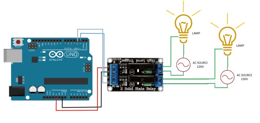
let's explore an example with a greater detail, describing the process of blinking two 220V lamps for 1 second and then deactivating them for 1 second using the 2-Channel 2 AMP Solid State Relay board:
In this illustrative scenario, we'll walk through a controlled lighting sequence involving two 220V lamps, showcasing the capabilities of the 2-Channel 2 AMP Solid State Relay board in orchestrating this dynamic operation.
Library:
This Module doesn't need a library to work.
Code:
This code is designed to control the blinking of two LEDs (connected to pins 2 and 3) in a specific sequence. It demonstrates how to alternate the illumination of these LEDs, creating a blinking pattern, and it provides status updates via the serial monitor.
// Define the LED pins
const int ledPin1 = 2;
const int ledPin2 = 3;

void setup() {
  // Initialize digital pins as outputs
  pinMode(ledPin1, OUTPUT);
  pinMode(ledPin2, OUTPUT);

  // Turn off the LEDs initially
  digitalWrite(ledPin1, HIGH);
  digitalWrite(ledPin2, HIGH);

  // Initialize serial communication
  Serial.begin(9600);
  Serial.println("LED Blinking Sequence Started");
}

void loop() {
  // Turn on LED 1
  digitalWrite(ledPin1, LOW);
  digitalWrite(ledPin2, HIGH);
  Serial.println("LED 1 ON");
  delay(1000); // Wait for a second

  // Turn on LED 2
  digitalWrite(ledPin1, HIGH);
  digitalWrite(ledPin2, LOW);
  Serial.println("LED 2 ON");
  delay(1000); // Wait for a second

  // Turn off both LEDs
  digitalWrite(ledPin1, HIGH);
  digitalWrite(ledPin2, HIGH);
  Serial.println("Both LEDs OFF");
  delay(1000); // Wait for a second
}
-
Pin Definitions:
const int ledPin1 = 2;: Defines a constant namedledPin1and assigns it the value 2. This indicates that pin 2 will control the first LED.const int ledPin2 = 3;: Defines another constant namedledPin2and assigns it the value 3. This indicates that pin 3 will control the second LED.
-
Setup Function:
pinMode(ledPin1, OUTPUT);: Configures pin 2 as an output, indicating it will control an LED.pinMode(ledPin2, OUTPUT);: Configures pin 3 as an output, indicating it will control the other LED.digitalWrite(ledPin1, HIGH);: Turns off the first LED by setting pin 2 to a HIGH (off) state.digitalWrite(ledPin2, HIGH);: Turns off the second LED by setting pin 3 to a HIGH (off) state.Serial.begin(9600);: Initializes serial communication with a baud rate of 9600.Serial.println("LED Blinking Sequence Started");: Sends a message to the serial monitor indicating that the LED blinking sequence has started.
-
Loop Function:
digitalWrite(ledPin1, LOW);: Turns on the first LED by setting pin 2 to a LOW (on) state.digitalWrite(ledPin2, HIGH);: Ensures the second LED remains off by setting pin 3 to a HIGH (off) state.Serial.println("LED 1 ON");: Sends a message to the serial monitor indicating that the first LED is turned on.delay(1000);: Pauses the program for 1 second.digitalWrite(ledPin1, HIGH);: Turns off the first LED by setting pin 2 to a HIGH (off) state.digitalWrite(ledPin2, LOW);: Turns on the second LED by setting pin 3 to a LOW (on) state.Serial.println("LED 2 ON");: Sends a message to the serial monitor indicating that the second LED is turned on.delay(1000);: Pauses the program for 1 second.- The above steps create a sequence where the first LED blinks for 1 second, followed by the second LED blinking for 1 second.
-
Turn Off LEDs:
digitalWrite(ledPin1, HIGH);: Turns off the first LED by setting pin 2 to a HIGH (off) state.digitalWrite(ledPin2, HIGH);: Turns off the second LED by setting pin 3 to a HIGH (off) state.Serial.println("Both LEDs OFF");: Sends a message to the serial monitor indicating that both LEDs are turned off.delay(1000);: Pauses the program for 1 second.
Technical Details:
- Supply voltage: 5V DC
- Number of channels: 2
- Quiescent current: 0mA
- Maximum operating current: 26.8mA
- Trigger mode: high-level trigger
- Load voltage: AC 240V
- Load current: 2A
- Module life: 10 million times
- Switch the maximum frequency: 5KHz
- DC 0 – 2.5V Relay is OFF
- DC 3.3 – 5.0V Relay is ON
Resources:
Comparisons:
- While electromechanical relays (EMRs) and solid-state relays (SSRs) both serve the purpose of controlling electrical loads, they operate using distinct principles and have different characteristics.
- EMRs utilize coils, magnetic fields, springs, and mechanical contacts to switch the power supply, while SSRs rely on the electrical and optical properties of solid-state semiconductors, having no moving parts. This fundamental difference enables SSRs to perform input to output isolation and switching functions more efficiently and reliably.
- One notable advantage of SSRs is their ability to provide complete electrical isolation between input and output contacts, similar to EMRs. However, unlike EMRs, SSRs achieve this isolation without physical contacts, leading to enhanced durability and longevity. Their output functions like a conventional electrical switch, offering very high resistance when nonconducting (open) and very low resistance when conducting (closed).
- It is essential to note that while SSRs excel in driving AC loads, they are not designed to handle DC loads, unlike traditional relays that are versatile enough to work with both AC and DC loads. Additionally, EMRs can handle higher current capacities compared to SSRs, making them more suitable for certain high-power applications.
- you can check this **item** if you want more current.