Out Of Stock
Description
The A9G GPS Tracker is an IoT (Internet of things) Solution-based product that integrates a micro Controller ATSAMD21G18, GRRS/GSM+GPS module A9G with best power management and storage. The A9G Module is best suited for real IoT projects such as smart-home, outdoor monitoring, long-distance monitoring, GPS Tracker, etc. The module can be operated using 3.7V Lithium-Ion Battery as it requires a 3.5~4.2V typical 4.0V supply. The power consumption of this module ranges from 1.03mA to 1.14mA depending upon the application.
Features:
- Complete quad-band GSM / GPRS module, 800/900/ 1800/1900MHz
- SMD package for easy MP & testing
- Low power mode, average current 2mA or less
- Supports digital audio and analog audio, supports HR, FR, EFR, AMR voice coding
- Support voice calls and SMS messages
- Embedded network service protocol stack
- Support standard GSM07.07,07.05AT command and Anxin expandable command set
- Support PBCCH
- Supports firmware upgrade via serial port
Main specifications:
- A9/A9G size: 19.2*18.8*2.7mm (±0.2mm)
- Working temperature -30 ° C +80 ° C;
- Working voltage is 3.5V-4.2V, 4V power supply is recommended;
- Boot voltage > 3.5V;
- Low power average current is below 2ma;
- Support GSM/GPRS, four frequency bands, including 850, 900, 1800, 1900MHZ;
- GPRS Class 10;
- Sensitivity <-105;
- Support voice calls;
- Support SMS SMS;
- GPIO level is 2.8V;
- Support GPRS data service, maximum data rate, download 85.6Kbps, upload 42.8Kbps;
- Support standard GSM07.07, 07.05 AT commands and Ai-Thinker extension commands;
PinOut of the GSM GPRS GPS BD A9G Development Board:

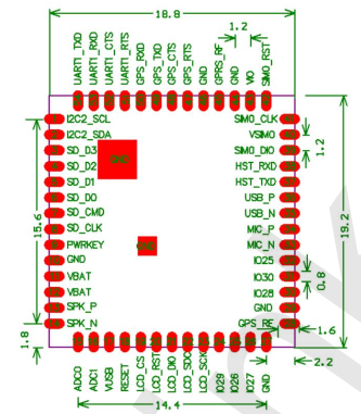
I2C2_SCL - I2C2 clock pin
I2C2_SDA - I2C2 data pin
SD_D3 - SD serial data pin
SD_D2 - SD serial data pin
SD_D1 - SD serial data pin
SD_D0 - SD serial data pin
SD_CMD - SD command pin
SD_CLK - SD clock pin
PWRKEY - the power button gives the pin a Low signal on
VBAT - lithium battery pin, connect the external power supply to this pin 3.5V-4.2V, the max supply current should be not less than 2A
SPK_P - Speaker positive (+) pin
SPK_N - Speaker negative (-) pin
ADC0 - ADC 0 pin (max. input 1.8V)
ADC1 - ADC 1 pin (max. input 1.8V)
VUSB - USB power supply pin (external power supply)
RESET - Module hardware reset pin. When this pin used the LOW level is <0.05V and the current is around 70 mA. Must use NMOS tube control and ground can not have leakage when it is working normally, otherwise, it will cause the module to be unstable and difficult to register to the network.
LCD_CS -LCD CS pin
LCD_RST - LCD reset pin
LCD-DIO - LCD DIO pin
LCD_SDC - LCD SDC pin
LCD_SCK - LCD SCK pin
IO29 - special function pin. After the module is working normally with the AT command, pull the pin LOW to enter the shutdown mode.
IO26 - General purpose IO pin. Do not add a pull-up resistor, the level can not be HIGH at power-on. Remark: it is a low-power indicator pin - if there is data, SMS, or a wake-up call it will be a 50 ms pulse.
IO27 - General purpose IO pin. Do not add a pull-up resistor, the level can not be HIGH at power-on. Remark: the default is 0 as the network status indicator.
GPS_RF - The GPS antenna pin can be connected to the antenna. If the circuit is connected to the PCB please pay attention to the 50 Ohm trace on the PCB (valid for A9G only)
GND - Ground pin
IO28 -General purpose IO pin. Do not add a pull-up resistor, the level can not be HIGH at power-on. Remark: default as GPS status indicator IO pin.
IO30 -General purpose IO pin.
IO25 - General purpose IO pin. Low-power pin and when the LOW signal enters to low-power mode.
MIC_N - Microphone negative (-) pin
MIC_P - Microphone positive (+) pin
USB_N - USB D- pin
USB_P - USB D+ pin
HST_TXD - firmware upload pin (transmit pin). pin level 2.8V, compatible with 3V3 (5V not compatible)
HST_RXD - firmware upload pin (receive pin). pin level 2.8V, compatible with 3V3 (5V not compat