AED 26.25
Description
The 2-channel PWM signal generator module is used to generate square wave signals for various experimental and development purposes. It can be used to drive stepping motor drivers, generate adjustable pulses for microcontroller units (MCUs), and control relative circuits using pulse width modulation (PWM) to adjust factors like blinking speed. The module supports serial port control with specific communication settings. It allows users to set the PWM frequency and duty cycle using designated commands. The module also provides parameter settings through a 3-channel keypad.
Package Includes:
- 1 x Signal Generator Module 2 Way PWM Pulse Frequency Duty Cycle Adjustable
Features:
- Dual Channel PWM: The module supports two independent PWM channels, labeled PWM1 and PWM2, allowing for the simultaneous generation of square wave signals on both channels.
- Adjustable Pulse Frequency: The module provides the ability to adjust the frequency of the generated square wave signals. It supports a wide range of frequencies, including 1Hz to 999Hz, 0.1KHz to 99.9KHz, and 1KHz to 150KHz.
- Adjustable Duty Cycle: Users can also adjust the duty cycle of the generated square wave signals. The duty cycle determines the ratio of the signal's high time to its total period. The module allows duty cycle values to be set from 1% to 100%.
- Stepping Motor Driver Support: The module is specifically designed to drive stepping motor drivers by providing the necessary square wave signals required for their operation.
- MCU Integration: It can generate adjustable pulses suitable for use with microcontroller units (MCUs). This feature enables precise timing and synchronization with other MCU-based circuits or systems.
- Serial Port Control: The module can be controlled via a serial port interface. It supports communication at a standard baud rate of 9600 bps and follows a specific communication protocol for sending commands and receiving responses.
- Parameter Settings: The module features a 3-channel keypad with dedicated buttons for Set, Up, and Down functions. These buttons allow users to access and modify various parameter settings such as PWM frequency and duty cycle.
- Setting Feedback: The module provides feedback on the success or failure of parameter settings. It indicates successful settings with the message "DOWN" and unsuccessful settings with the message "FALL."
- Easy Parameter Shifting: By short-pressing the Set button on the keypad, users can cycle through and display four different parameter values, including PWM1 frequency, PWM1 duty cycle, PWM2 frequency, and PWM2 duty cycle. The currently selected parameter flashes on the display.
- User-Friendly Interface: The module offers a straightforward and intuitive interface, making it easy for users to adjust settings and operate the signal generator efficiently.
Description:
The 2-channel PWM Pulse Frequency Adjustable Duty Cycle Square Wave Rectangular Wave Signal Generator Module is a versatile device designed for generating square wave signals in experimental and development scenarios. It offers a range of features and functionalities that make it suitable for a variety of applications. The module is equipped with two independent PWM channels, PWM1 and PWM2, allowing users to generate square wave signals simultaneously on both channels. This dual-channel capability enables the module to drive multiple components or circuits simultaneously, providing flexibility in experimental setups. it has the ability to adjust the pulse frequency of the generated square wave signals. It supports a wide frequency range, allowing users to set frequencies from as low as 1Hz to as high as 150KHz. The frequency can be precisely tuned using specific command formats, such as setting it in Hertz (Hz), kilohertz (kHz), or a combination of kilohertz and hertz (X.X.X.). In addition to frequency adjustment, the module also provides the flexibility to adjust the duty cycle of the square wave signals. The module is particularly useful in driving stepping motor drivers, as it generates the required square wave signals for their operation. This capability makes it a valuable tool in various motor control applications, where precise control over motor movements is required.
Principle of Work:
-
The 2-channel PWM Pulse Frequency Adjustable Duty Cycle Square Wave Rectangular Wave Signal Generator Module operates by generating square wave signals on two independent PWM channels, PWM1 and PWM2. These square wave signals can be configured in terms of frequency and duty cycle to meet specific requirements. Here's an overview of how the module works and how to configure it:
-
Power Supply: Connect the power supply to the module, ensuring that the voltage and current specifications are compatible.
-
Serial Port Control: The module supports communication through a serial port interface. Connect a device capable of serial communication (such as a computer or microcontroller) to the module's serial port.
-
Communication Settings: Configure the communication settings of the connected device to match the module's specifications. The module uses the following communication settings:
- Baud Rate: 9600 bps
- Data Bit: 8
- Stop Bit: 1
- Verify Bit: None
- Flow Control: None
-
Configuration Commands: To configure the module, you need to send specific commands through the serial port. The module recognizes command patterns to set parameters such as PWM frequency and duty cycle. Here are some example command patterns:
- "S1FXXXT": Sets PWM1 frequency as XXX Hz (001 to 999).
- "S1FXX.XT": Sets PWM1 frequency as XX.X KHz (00.1 to 99.9).
- "S1F:X.X.X.T": Sets PWM1 frequency as XXX KHz (0.0.1 to 1.5.0).
- "S1DXXXT": Sets PWM1 duty cycle as XXX (001 to 100).
- "S2DXXXT": Sets PWM2 duty cycle as XXX (001 to 100).
-
Adjusting Parameter Values: To modify parameter values, use the keypad provided on the module. The keypad consists of Set, Up, and Down buttons. Here's how to use it:
- Short-press the Set button: This cycles through the four parameter values, such as PWM1 frequency, PWM1 duty cycle, PWM2 frequency, and PWM2 duty cycle. The currently selected parameter will flash on the display.
- Use the Up and Down buttons: After selecting the desired parameter, use the Up button to increase the value and the Down button to decrease the value. This allows for easy adjustment of the parameter values.
-
Setting Feedback: After sending configuration commands or adjusting parameter values, the module provides feedback on the success or failure of the settings. A successful setting is acknowledged with the message "DOWN," while an unsuccessful setting is indicated by the message "FALL."
-
Additional Parameter Settings: The module also features a 3-channel keypad with Set, Up, and Down buttons for additional parameter settings. These settings may include aspects such as frequency range and duty cycle range.
-
Experimentation and Development: Once the module is configured according to your requirements, you can use the generated square wave signals to drive stepping motor drivers, control relative circuits, or perform experiments and developments that require adjustable square wave signals.
-
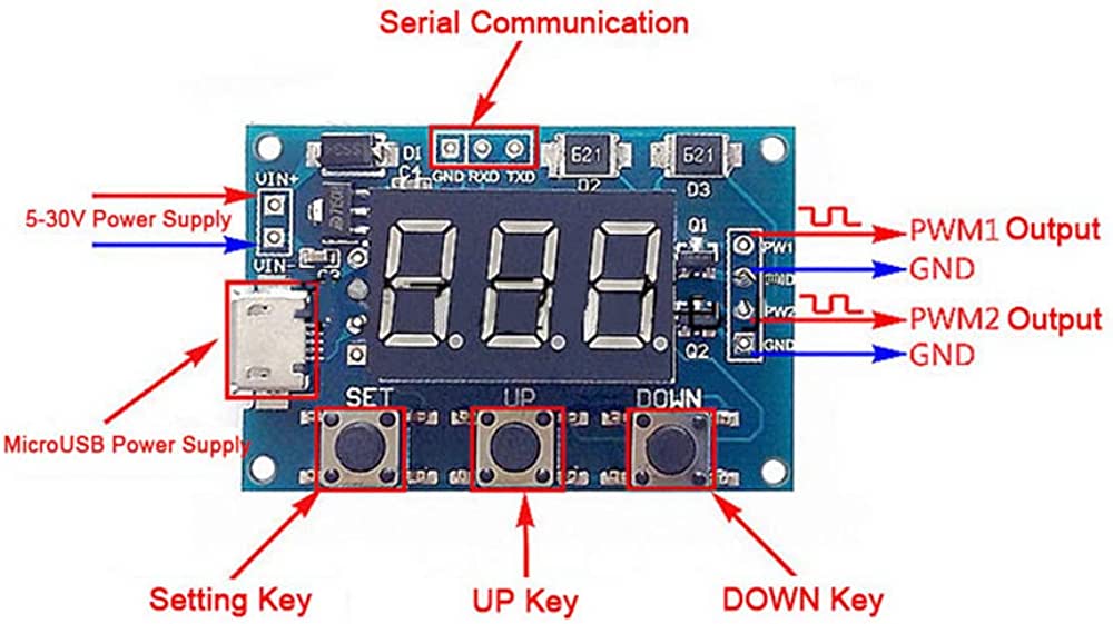
Pinout of the Module:
Applications:
- Motor Control: The module can be used to drive stepping motor drivers by generating square wave signals with adjustable frequencies and duty cycles. It enables precise control over motor movements and is useful in applications such as robotics, automation, and CNC machines.
- Electronics Testing and Development: The module is valuable for testing and developing electronic circuits and systems. It can generate square wave signals for circuit characterization, functional testing, and prototyping. The adjustable pulse frequency and duty cycle allow for fine-tuning and analysis of circuit behavior.
- Microcontroller Projects: The module is suitable for generating adjustable pulses required in microcontroller-based projects. It enables synchronization with microcontrollers, allowing precise timing and control of various functions and peripherals.
- Signal Generation and Simulation: The module can generate square wave signals for signal generation and simulation purposes. It can be used to simulate various square wave signal scenarios required in communication systems, signal processing, and waveform analysis.
- PWM Control: The module's ability to generate adjustable pulse width modulation (PWM) signals makes it useful in applications requiring control of lighting intensity, speed regulation of motors, and power control for various devices.
- Research and Education: The module serves as an educational tool for teaching and learning about pulse frequency and duty cycle modulation, motor control, signal generation, and microcontroller integration. It can be utilized in laboratories, research projects, and educational institutions.
- Prototyping and DIY Projects: The module is beneficial for electronics enthusiasts and makers involved in prototyping and DIY projects. It provides flexibility in generating and controlling square wave signals for various custom applications and experiments.
Circuit:
No circuit is needed it can work out of the box.
Library:
No library is needed.
Code:
No code was used.
Technical Details:
- 1.Operating Voltage:5-30V,support micro USB 5.0V power supply
- 2. Frequency Range:1Hz~150KHz
- 3. Frequency Precision:2%
- 4. Signal Load Capacity: output current is within 8--30mA
- 5. Output Range: default 5V V-pp (can be changed by external power)
- 6. Ambient Temperature:-30℃~70℃
Resources:
Comparisons:
We will compare the 2-channel PWM Pulse Frequency Adjustable Duty Cycle Square Wave Rectangular Wave Signal Generator Module and the Signal Generator Module Adjustable Square Wave NE555 based on several factors:
- Number of Channels:
- 2-channel PWM Module: It provides two independent PWM channels, PWM1 and PWM2, allowing for the simultaneous generation of square wave signals on both channels.
- NE555 Signal Generator Module: It typically provides a single channel for generating square wave signals.
- Frequency and Duty Cycle Range:
- 2-channel PWM Module: It offers a wider frequency range, supporting frequencies from 1 Hz to 150 KHz. The duty cycle can be adjusted from 1% to 100%.
- NE555 Signal Generator Module: The frequency and duty cycle range may vary depending on the specific module design and implementation. However, it is commonly used for generating square waves in the audio frequency range (up to a few tens of kHz) with adjustable duty cycles.
- Pulse Width Modulation (PWM) Capability:
- 2-channel PWM Module: It specifically includes PWM capability, allowing precise control of the duty cycle of the generated square wave signals. This feature is useful for applications such as motor control, lighting control, and power regulation.
- NE555 Signal Generator Module: While it can generate square waves, it may not have built-in PWM functionality. The duty cycle adjustment may be limited or not available, making it more suitable for basic square wave generation rather than PWM applications.
- Control and Configuration:
- 2-channel PWM Module: It supports configuration and control via a serial port interface. The provided command patterns allow for the convenient setting of PWM frequency and duty cycle values.
- NE555 Signal Generator Module: The NE555 module usually requires manual adjustment of resistor and capacitor values to set the desired frequency and duty cycle. It may not have a built-in interface for digital control or configuration.
- Application Focus:
- 2-channel PWM Module: It is specifically designed for applications that require precise control of square wave signals, such as driving stepping motor drivers, microcontroller projects, and circuit testing and development.
- NE555 Signal Generator Module: It is a versatile and widely used module for basic square wave generation. It is commonly employed in educational settings, simple electronic projects, and as a basic timing element in circuits.