AED 144.50
Description
The PICkit3.5 is a low-cost hardware debugger and programmer that utilizes in-circuit logic debugging built into each chip with Flash memory. It is a 3.5 Kit that includes the necessary cables and provides more features, faster speed, and more stable simulation than PICkit2. The programmer supports various MCUs such as PIC16, PIC18, PIC24, DSPIC, etc., and offers features such as offline programming, MPLAB IDE compliance, real-time, and built-in overvoltage/short circuit monitor.
Package Includes:
- 1 x PICkit3.5 Debugger and Programmer Kit
- 1x USB cable
- 1x jumper wire
Features:
- Offline programming for smooth downloads and compatibility with all versions of MPLAB and MPLAB X.
- Each PICkit 3.5 has a single serial number, enabling operation with multiple Kit3.5 devices under MPLAB X.
- Increased external power supply current for more stable output voltage.
- Enhanced interface protection.
- Full-speed USB 12 Mbit/s host PC interface.
- Real-time operation.
- MPLAB IDE-compliant execution with a free download from Microchip.
- Built-in overvoltage and short-circuit monitor.
- Firmware is upgradable from PC or web download.
- Fully enclosed design.
- Diagnostic LED (power, busy, error).
- Ability to read/write microcontroller memory data.
- Space clearing with verification of program memory.
- Peripheral freeze at the breakpoint.
- Capability to program up to 512K byte flash with the Programmer-to-Go.
- ICSP cable is included in the package.
Description:
The PICkit3.5 Programmer In-Circuit Debugger is a low-cost hardware debugger and programmer designed for PIC microcontrollers. It uses in-circuit logic debugging built into each chip with Flash memory. The kit includes the necessary cables and has several features such as offline programming, and compatibility with all versions of MPLAB, MPLAB X, and other MCUs. The PICkit 3.5 has increased the external power supply current for stable output voltage and interface protection. It also has a real-time diagnostic LED for power, busyness, and error, as well as the ability to read/write and clear space with verification program memory. The package includes the PICkit3.5, USB cable, jumper wire, and ICSP cable. It is used for programming, debugging, code dumping, flashing, and firmware updates of PIC microcontrollers. PICkit3.5 uses the same connection as PICkit 3.
Principle of Work:
The PICkit 3.5 Kit is a low-cost hardware debugger and programmer for PIC microcontrollers. It works by utilizing in-circuit logic debugging built into each chip with Flash memory. This allows PICkit 3.5 to simulate and download PIC16, PIC18, PIC24, DSPIC, and other MCUs.The kit can be used to program and debug PIC microcontrollers, perform code dumping in the production process, and update the firmware. It also includes offline programming that allows for smooth downloads and complete compatibility with all versions of MPLAB and MPLAB X. The PICkit 3.5 has several features that set it apart from its predecessor, the PICkit 2. It is faster and has a more stable simulation, and it can program up to 512K byte flash with the Programmer-to-Go. The kit also includes a built-in over-voltage/short-circuit monitor and firmware that can be upgraded from a PC or web download. The PICkit 3.5 connects to the target PIC microcontroller through a 6-pin In-Circuit Serial Programming (ICSP) connector. The kit includes an ICSP cable for this purpose. The 6-pin ICSP connector includes pins for the MCLR/Vpp reset pin, target voltage, ground, program data, program clock, and a reserved pin.
Pinout of the Module:

| Pin Number | Pin Name | Description |
|---|---|---|
| 1 | MCLR/Vpp | Connected to the Master clear external reset pin of PIC to reset the MCU before programming |
| 2 | VDD | Target voltage of PIC, 5V or 3.3V |
| 3 | Ground | Ground pin of the system |
| 4 | PGD/ICSPDAT | Program Data(PDG) is connected to the In Circuit Serial Programming (ICSP) data pin |
| 5 | PGC/ICSPCLK | Program Clock (PGC) is connected to In Circuit Serial Programming (ICSP) clock pin |
| 6 | No connection | This pin is reserved for future use |
Applications:
- Programming and debugging PIC microcontrollers
- Code dumping in the production process
- Firmware update or flashing
- Verifying microcontroller memory data
- Freeze peripherals at the breakpoint
- Simulating and downloading PIC16, PIC18, PIC24, DSPIC, and other MCUs
- In-circuit logic debugging
- Low-cost hardware debugging and programming
- DIY projects and hobbyist use.
Circuit:
To connect the PICKit3.5 with PIC Microcontrollers following connections are used
- Pin 1 of the burner with Pin4 of the PIC Microcontroller
- Pin 2 of the burner with Pin14 of the PIC Microcontroller
- Pin 3 of the burner with Pin 5 of the PIC Microcontroller
- Pin 4 of the burner with Pin 13 of the PIC Microcontroller
- Pin 5 of the burner with Pin 12 of the PIC Microcontroller
- Pin 6 is not connected for normal usage.
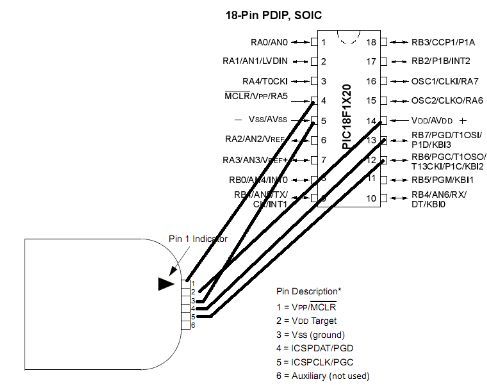
This configuration is only for PIC18F1x20. Every microcontroller pin configuration will be different and you can consult the datasheet of your respective microcontroller for this these connections.
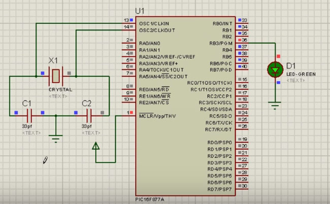
Project:
Connect the following circuit. You don’t need to connect the Crystal oscillator and capacitor. Just connect LEDs, Power, and resistors. You will provide connections from the programmer board to LEDs.
- To begin, download the MPLAB IPE software from the internet and install it, along with any required drivers.
The steps to install MPLAB IPE:
- Go to the Microchip website and navigate to the MPLAB IPE download page.
- Choose the version of MPLAB IPE that is compatible with your operating system and download the installer.
- Once the download is complete, run the installer.
- Follow the prompts to complete the installation process.
- When prompted, select the components that you want to install.
- After the installation is complete, connect your hardware device to your computer using a USB cable.
- Open MPLAB IPE and select your device from the list of available devices.
- Click on the "Connect" button to establish a connection between your device and MPLAB IPE.
- Next, open the mikroC PRO for PIC software and write a program that utilizes two LEDs - one in sinking mode and one in sourcing mode. In sinking mode, writing a 0 will turn the LED off, while writing a 1 will turn it on. In sourcing mode, writing a 1 will turn the LED off, and writing a 0 will turn it on.
- Once the program is written, generate a .hex file.
- To generate the .hex file, you first need to write a program using the mikroC PRO for PIC software then, select the "Project" menu and click "Build All" to generate the .hex file. The .hex file will be saved in the project's "Output" folder.
- Connect the Programmer board to your PC using a USB cable.
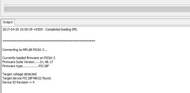
- Open the MPLAB IPE software and select your specific microcontroller. Click "connect" and then "OK" when prompted.
- Wait for the output section to show something like this one.
To import the hex file, navigate to the file menu bar and select the import option. Then, open the folder where you have saved the .c file for your mikroC program and choose the .hex file. Next, press the program button and observe the LED blinking as a result.
Library:
To install the XC.h library for the Microchip XC8 compiler, follow these steps:
- Download the library file from the Microchip website. Make sure to download the version that is compatible with your compiler.
- Extract the downloaded ZIP file to a temporary folder on your computer.
- Copy the extracted "xc.h" file to the "inc" folder in the XC8 installation directory. The default installation path is "C:\Program Files (x86)\Microchip\xc8
\inc".
Code:
This is a simple PIC code to blink LEDs connected to pins 33 and 34 of the PIC18F46K22:
#include "xc.h" // include the XC8 header file

// Configuration settings
#pragma config FOSC = INTIO67, WDTE = OFF, PWRTE = OFF, MCLRE = ON, CP = OFF, BOREN = OFF, LVP = OFF, WRT = OFF

#define _XTAL_FREQ 16000000 // define the frequency

// main function
void main(void)
{
    // set the TRIS registers to configure the LED pins as outputs
    TRISDbits.TRISD1 = 0; // Pin 33
    TRISDbits.TRISD2 = 0; // Pin 34

    // infinite loop
    while(1)
    {
        LATDbits.LATD1 = 1; // turn on LED1
        LATDbits.LATD2 = 0; // turn off LED2
        __delay_ms(500); // delay for 500 milliseconds

        LATDbits.LATD1 = 0; // turn off LED1
        LATDbits.LATD2 = 1; // turn on LED2
        __delay_ms(500); // delay for 500 milliseconds
    }
}
Note that this code assumes that the LEDs are connected to pins RD1 and RD2 of the PIC18F46K22, which are connected to pins 33 and 34 on some development boards. You may need to modify the code if your LEDs are connected to different pins. Also, make sure that you have selected the correct oscillator frequency in the configuration settings.
Technical Details:
- USB Full speed 12 Mbit/s host PC interface
- Built-in overvoltage/short circuit monitor
- Diagnostic LED (power, busy, error)
- Supports program read/write and microcontroller memory data clear space with verification program memory
- Supports programming of up to 512K byte flash with the Programmer-to-Go
- External power supply current output voltage is more stable
- Interface protection is perfect
- Supports PIC16, PIC18, PIC24, dsPIC, and other MCUs.
Resources:
Comparisons:
PICkit 3.5 is an improved version of PICkit 2, with several new features and improvements. Here are some of the differences between the two:
- Target Devices: PICkit 3.5 supports a wider range of microcontrollers compared to PICkit 2, including PIC16, PIC18, PIC24, DSPIC, and other MCUs.
- Debugging: PICkit 3.5 provides a faster and more stable debugging experience than PICkit 2. It has a built-in overvoltage/short circuit monitor and supports real-time debugging.
- Offline Programming: PICkit 3.5 has offline programming capability, which means that the programming process will not stop even if the connection to the PC is lost.
- Interface Protection: The interface protection in the PICkit 3.5 is more robust compared to PICkit 2.
- Firmware Upgradable: The firmware of the PICkit 3.5 is upgradable from the PC or through web downloads, whereas the PICkit 2 firmware is not upgradeable.
- Power Supply: PICkit 3.5 has an increased external power supply current and a more stable output voltage compared to PICkit 2.