AED 39.50
Description
The Digispark ATTINY 167 is an advanced and compatible Clone version of the Digispark Pro. Mirroring its counterpart's exceptional performance and pinout, the ATTINY 167 boasts an impressive array of features. Among its highlights are 13 versatile digital pins, with 11 of them doubling as ADC pins, I2C, and SPI interfaces. Notably, this iteration rectifies a common absence in Digispark boards by incorporating a UART on pins 6 and 7. What's more, the ATTINY 167 integrates Native USB functionality directly into the chip, empowering the board to seamlessly transform into a keyboard, mouse, or any desired Human Interface Device (HID). Your innovation knows no bounds with the Digispark ATTINY 167.
Package Includes:
- 1× Digispark Attiny167 Development Board (Pro Compatible)
Features:
- Compatibility: The board is fully compatible with Arduino IDE 1.5 on multiple operating systems, including OSX, Windows, and Linux.
- Easy Installation: It comes with fully signed drivers and an executable for hassle-free installation.
- USB Versatility: The board supports USB programming, USB device emulation, and USB-CDC virtual serial port emulation.
- Precise Clock: Equipped with a true 16MHz precision crystal, the 16 MHz AVR MCU ensures accurate timing.
- Flash Memory: The board boasts 16KB of Flash Memory, with approximately 14.5KB available after the bootloader is factored in.
- Serial Communication: It offers seamless serial communication over USB for debugging and data transfer.
- Versatile I/O Pins: With 14 I/O pins available, including 2 shared with USB functionality, the board provides ample connectivity.
- Communication Interfaces: The board supports various communication interfaces, including I2C, true SPI, UART, LIN, and USI.
- Analog-to-Digital Conversion: Featuring ADC capabilities on 10 pins, the board supports analog sensor integration.
- PWM Channels: It offers 3 PWM channels that can be assigned to a selection of pins, enhancing control over analog output.
- Power Options: The board can be powered via USB or an external source, with automatic voltage selection between 5V and 6-16V.
- On-Board Button: An on-board button can be used as a reset button, for programming, or as a user button. It can also be repurposed as a general I/O pin without affecting the bootloader.
- Built-In Regulator: The board incorporates a 150mA 5V regulator to ensure stable power supply.
- Status Indicators: Equipped with a power LED and a Test/Status LED (on Pin 1), the board provides visual feedback.
- Power Management: User-accessible solder jumpers enable the disabling of LEDs and other features to achieve lower power consumption.
- Mounting Holes: The presence of two mounting holes facilitates secure installation in various projects.
- Breadboard Compatibility: The board's pinout and spacing are breadboard-friendly, allowing for easy prototyping. (Note: Three side header pins are solely for legacy shield support.)
Description:
Introducing the Digispark Pro Micro USB Development Board your gateway to Arduino ATTiny167 compatibility. Experience effortless connectivity with the Micro USB interface, allowing direct USB connection via a Micro USB cable without the need for an additional USB to serial interface module. Featuring a robust offering of 14 digital IO connections and 10 analog ADC interfaces, the ATTiny167 board stands as an ultra-compact, budget-friendly, and open-source Arduino-compatible USB development platform. Distinguished from its basic Digispark counterparts, this board boasts an expanded array of benefits, including more pins, a generous program space, enhanced features, and heightened reliability. Notably, it seamlessly supports over 25 existing Digispark shield variations, with added capabilities like Wi-Fi, Bluetooth, BLE protection, and beyond. Equipped with a Micro USB Development Board, you're poised for success across your entire project spectrum. Explore the versatility, power, and convenience that this board brings to your creative endeavors.
Principle of Work:
the Digispark board's internal workings revolve around its microcontroller, open hardware design, compatibility with Arduino's software environment, USB communication facilitated by a bootloader and V-BUS library, and the collaborative power of libraries and the Arduino community:
- Microcontroller (MCU): The heart of the Digispark is a microcontroller, in this case, the ATTiny167. This MCU is a small integrated chip that houses a central processing unit (CPU), memory, and various I/O (input/output) interfaces. It is responsible for executing program instructions, handling data, and controlling external devices.
- Free Hardware Design: Digispark's hardware design is freely available, which means that anyone can access its blueprints and specifications. This open approach allows individuals and businesses to create their own versions of the board while ensuring compatibility with the established framework.
- Arduino Compatibility: The Digispark is designed to be compatible with the Arduino ecosystem. This means that it follows the principles and standards set by Arduino, making it easy to work with existing Arduino code and libraries.
- USB Connectivity: The Digispark features a Micro USB interface, which allows you to directly connect it to a computer using a Micro USB cable. Unlike some other development boards that require an external USB-to-serial adapter, the Digispark's integrated USB functionality simplifies the connection process.
- Bootloader and V-BUS Library: The Digispark employs an embedded bootloader. A bootloader is a small piece of software that initializes the MCU and handles tasks such as program uploading and communication with a computer. In the Digispark's case, the V-BUS library helps manage USB communication, allowing the board to interact with the computer as a USB device.
- Arduino IDE: The Arduino IDE (Integrated Development Environment) is a software platform used to write, compile, and upload code to the Digispark board. It provides a user-friendly interface for developers to create programs (sketches) that control the MCU's behavior.
- Programming: To program the Digispark, you write code using the Arduino IDE, compile it into a binary format, and then upload it to the board via the USB connection. The bootloader facilitates this process by receiving the uploaded code and storing it in the appropriate memory location.
- Libraries: The Digispark benefits from a wealth of libraries available online. Libraries are collections of pre-written code that simplify the interaction with various sensors, modules, and functionalities. These libraries abstract the complexity of hardware interactions, allowing developers to focus on higher-level programming tasks.
- Hardware Control: Within your code, you can control the Digispark's hardware features, such as its digital I/O pins, analog-to-digital converter (ADC) inputs, PWM (pulse-width modulation) outputs, and communication interfaces (I2C, SPI, UART).
- Community Collaboration: The Digispark ecosystem thrives on collaboration within the community. Developers share code, projects, and insights, contributing to the growth and enhancement of the platform.
Pinout of the Module:
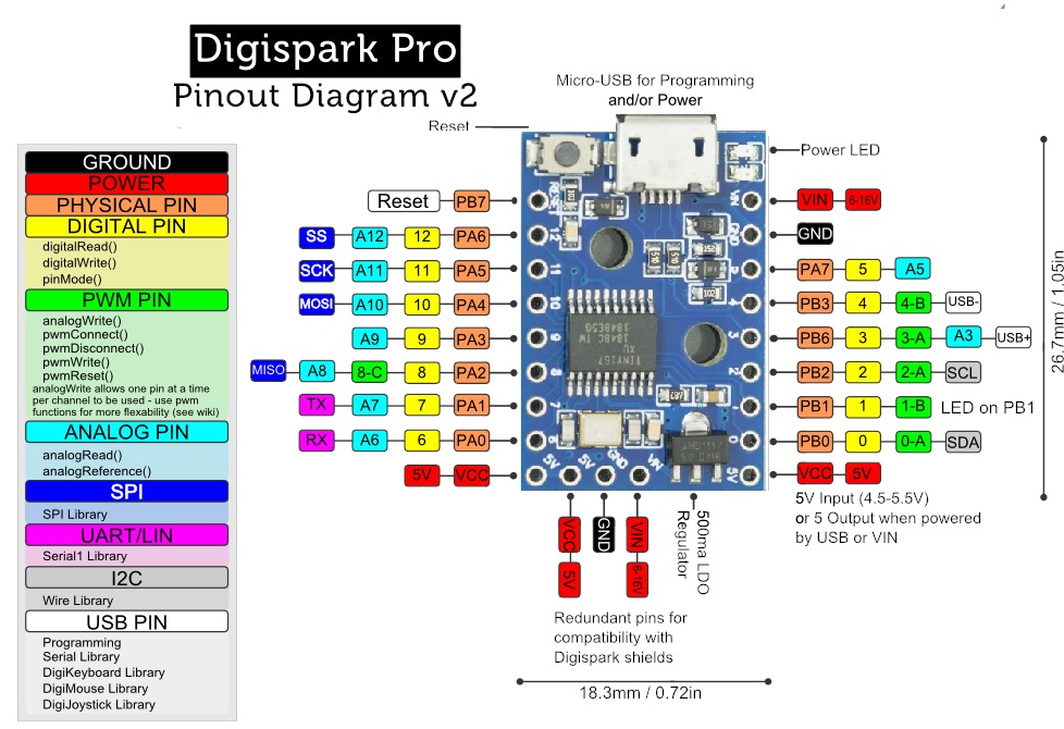
- 5V Power Pin: This pin provides a regulated 5V power output from the board, which can be used to supply power to external components.
- Ground Pins (GND): These pins are connected to the ground reference of the board and are crucial for completing electrical circuits and ensuring proper functioning.
- Digital I/O Pins (0-12): The Digispark offers 13 digital input/output pins, numbered 0 to 12. These pins can be configured as either digital input pins to read logic values (0 or 1) from external devices or digital output pins to drive various modules such as LEDs, relays, and more.
- PWM Pins: Among the available pins, 6 of them can be utilized as Pulse Width Modulation (PWM) outputs. PWM enables you to produce analog-like signals by varying the duty cycle of the square wave, allowing for precise control over devices like motors and LED brightness.
-
Analog Reference (AREF): This pin serves as a reference voltage (ranging from 0 to 5V) for analog inputs. It's used in conjunction with the
analogReference()function to set the upper limit of the analog input range. -
I2C Protocol:
- SDA (Serial Data): This pin is involved in I2C communication and is used for transmitting data between the Digispark and other devices.
- SCL (Serial Clock): This pin is the clock signal for I2C communication and synchronizes data transfer between devices.
-
UART Communication:
- Pins 6 and 7: These pins support UART (Universal Asynchronous Receiver-Transmitter) communication. UART is a common serial communication protocol used for establishing communication between the board and other devices, such as computers and sensors.
- USB Connection: The Digispark features a USB interface with software USB functionality enabled by the V-BUS library. This enables the board to emulate a USB port, even in the absence of a dedicated serial converter. To connect the board to a computer, you need to install the appropriate driver.
- OnBoard LED: There's a built-in LED connected to digital pin 1. When this pin is set to a HIGH value, the LED illuminates, and when it's set to LOW, the LED turns off. This LED can be useful for quick visual feedback in your projects.
- Analog Pins (A0-A7): The Digispark boasts 8 analog input pins (labeled A0 to A7) that enable you to read analog voltages from external sensors or devices. These pins are particularly useful for capturing data from the physical world.
- Vin (Voltage Input): This pin allows you to supply an external DC voltage input in the range of 7-12V to power the board and its components.
- Power LED Indicator: This LED serves as a power indicator. If the LED is illuminated, it indicates that the board is correctly powered on. If the LED is off, it could signify an incorrect connection or lack of power.
Applications:
- Industrial Machinery Controlling Systems: Digispark can serve as a compact and cost-effective controller for automating industrial machinery, monitoring processes, and managing equipment interactions.
- Solar Applications: In solar systems, Digispark can monitor solar panel output, regulate charge controllers, and control mechanisms for tracking the sun's position to optimize energy generation.
- IoT-Based Applications: With its small size and connectivity options, Digispark can be used in Internet of Things (IoT) projects to collect data from sensors, communicate with cloud services, and control connected devices.
- Power Supply and Charger-Based Applications: The board can control power supply units, battery charging, and voltage regulation, making it suitable for applications like battery management systems and portable charging solutions.
- Weather Sensor Systems: Digispark can gather data from weather sensors, process the information, and display or transmit weather-related data, enabling the creation of weather monitoring stations.
- Wireless Communication Applications: Utilizing wireless communication modules, Digispark can create wireless data transmission systems for remote monitoring, control, and data exchange.
- Security-Based Applications: The board can be integrated into security systems for tasks like sensor input processing, controlling alarms, and sending notifications, making it useful for home security, access control, and surveillance.
- Medical & Health Equipment: Digispark can be incorporated into medical devices to monitor patient data, control equipment functionality, and facilitate communication between medical instruments and systems.
- Automobile-Related Applications: It can be used for vehicle diagnostics, control of vehicle accessories, or even as part of autonomous vehicle projects, demonstrating its adaptability in the automotive sector.
Circuit:
We will not need any circuit, in this testing code, we will rely on the built-in LED on the 1 pin.
Connecting with First Time
-
Open Arduino IDE: If you haven’t already, download the Arduino IDE from the official software page: Arduino IDE Download.
-
Connect the Board to Your Computer:
- Open the Arduino IDE.
- From the top menu, select
File → Preferencesto open the Preferences dialog box. - In the
Additional Boards Manager URLs:box, paste the following URL: http://digistump.com/package_digistump_index.json. If you have multiple URLs, separate them with commas. - Click the
OKbutton.
-
Installing Digispark Board Support Package:
- In the Arduino IDE, navigate to
Tools → Board → Boards Manager…to open the Boards Manager window. - Type
Digisparkinto the search field at the top of the Boards Manager dialog box window. - After filtering, you'll see
Digistump AVR Boards. Click on theInstallbutton for the Digistump item. - Wait for the package to install, then click the
Closebutton.
- In the Arduino IDE, navigate to
-
Install Digispark Windows 10 Drivers:
- Download the Digispark Digistump Drivers for Windows.
- Extract the downloaded
Digistump.Drivers.zip. - On a 64-bit Windows computer, double-click
DPinst64.exe; on a 32-bit Windows computer, double-clickDPinst.exeto install the Digispark drivers. - Click the
Installbutton when prompted. - If a dialog box appears displaying "Windows can’t verify the publisher of this driver software," click the
Install this driver software anywaybutton.
-
Select Board:
- The Digispark follows a slightly different programming procedure compared to some other Arduino-compatible boards.
- From the
Toolsmenu, selectBoard → Digispark pro(16Mhz). - Note that the
Tools → ProgrammerandTools → Portselections do not matter for Digispark programming.
-
Upload a Sketch:
- Write your code or open a Digispark example in the Arduino IDE.
- Click on the upload button (do not connect the Digispark to your PC yet).
- During the upload, the bottom status box will prompt you to plug in your Digispark. At this point, either plug it in or unplug and replug it.
- You’ll observe the upload progress, followed by the immediate execution of your code on the Digispark.
-
Code Execution Delay:
- If you unplug the Digispark and then plug it back in or connect it to another power source, there will be a 5-second delay before your programmed code runs. This delay allows Digispark to check if you are attempting to reprogram it.
Code:
This is a simple Arduino sketch that controls the onboard LED of the Digispark board, causing it to blink on and off in a repeating pattern:
// Define constants for better readability
const int onboardLED = 1;   // Onboard LED is connected to port 1 of Attiny167
const int blinkInterval = 200; // Blink interval in milliseconds

void setup() {
  pinMode(onboardLED, OUTPUT);
}

void loop() {
  digitalWrite(onboardLED, HIGH); // Turn on the LED
  delay(blinkInterval);
  digitalWrite(onboardLED, LOW);  // Turn off the LED
  delay(blinkInterval);
}
-
Initialization (
void setup()):- The
setupfunction is called once when the Digispark board starts. pinMode(onboardLED, OUTPUT);configures the specified pin (onboardLED, which is pin 1) as an output pin. This prepares the pin to control the onboard LED.
- The
-
Looping (
void loop()):- The
loopfunction contains a continuous loop that runs after the setup is complete. digitalWrite(onboardLED, HIGH);sets the voltage level of the specified pin (onboardLED) to HIGH, which turns on the onboard LED, making it emit light.delay(blinkInterval);causes a pause in the program execution for the specified time (blinkInterval), which is 200 milliseconds in this case.digitalWrite(onboardLED, LOW);sets the voltage level of the specified pin (onboardLED) to LOW, turning off the onboard LED.delay(blinkInterval);another delay follows, creating an equal pause before the loop restarts.
- The
-
Repeating:
- The loop continuously repeats, resulting in a pattern where the onboard LED blinks on for 200 milliseconds, then off for 200 milliseconds, creating a visible blinking effect.
Technical Details:
- Microcontroller - ATtiny167
- Clock frequency - 16 MHz (8bit)
- inputs/outputs
- Overall – 14th
- digital pins – 14
- digital PWM pins – 3
- analog pins - 11
- connections
- I²C, SPI, UART, LIN and USI
- Storage
- SRAM - 512 bytes
- EEPROM - 512 bytes
- Flash Memory - 16KB
- Current & Voltage
- Operating Voltage - 5V/DC
- via USB or VIN pin
- max. current per IO pin – 40mA
- Operating Voltage - 5V/DC
- Dimensions (L x W x H) - 26.7mm x 18.3mm x 4mm
- Weight - 4g
Resources:
- Arduino IDE Download
- The reference for the language
- Digispark Digistump Drivers for Windows.
- Handbook of the C++ language
- Getting to know the Arduino IDE
- Digispark programming features
- ATtiny167 Datasheet
Comparisons:
The comparison between the Digispark ATTINY167 Development Board (Pro Compatible) and the Arduino IDE can be categorized into two aspects: the hardware board itself and the integrated development environment (IDE):
Hardware Board Comparison:
-
Digispark ATTINY167 Development Board:
- The Digispark ATTINY167 board is a compact development platform that features the ATTINY167 microcontroller. It offers features like digital I/O pins, analog inputs, PWM outputs, USB connectivity, and more.
- The board is designed to be Arduino-compatible, which means it can be programmed using the Arduino IDE and follows Arduino programming paradigms.
- Its compact size and features make it suitable for smaller projects, prototyping, and situations where space is limited.
- Notable features include USB-CDC virtual serial port emulation, multiple communication interfaces (I2C, SPI, UART), onboard LED, and the ability to function as a USB human interface device (HID).
-
Arduino IDE:
- The Arduino IDE (Integrated Development Environment) is a software platform that facilitates writing, compiling, and uploading code to various microcontroller platforms, including Arduino boards and compatible boards like the Digispark.
- The IDE provides a user-friendly interface for writing and managing code, libraries, and projects.
- It offers a wide range of built-in functions, libraries, and examples that simplify programming tasks.
- The Arduino IDE supports a variety of Arduino boards, each with its own set of features and capabilities.
Integrated Development Environment (IDE) Comparison:
-
Digispark ATTINY167 Development Board:
- The Digispark ATTINY167 board can be programmed using the Arduino IDE. However, due to its compact size and unique features, it might require specific libraries or configurations that are tailored to its hardware.
-
Arduino IDE:
- The Arduino IDE is a versatile and widely used software tool that supports a broad range of Arduino boards and derivatives.
- It offers a user-friendly code editor, a comprehensive library manager, and a straightforward interface for uploading code to boards.
- The IDE provides a consistent development experience across various Arduino boards, including boards from different manufacturers.