AED 17.85
Description
Rotary encoders, a fundamental component in modern electronics and control systems, play a crucial role in translating mechanical rotation into precise electrical signals. These devices are adept at monitoring and encoding the extent and direction of rotation from a rotary input device, such as a knob. Their application spans a wide range of industries, from robotics and automotive systems to consumer electronics and industrial automation.
Package Includes:
- 1 x Rotary Encoder Module Potentiometer Without Knob
Features:
- Precise Position Sensing: The rotary encoder module is designed to provide highly accurate position sensing based on the amount and direction of rotation. This precision is vital for applications requiring fine-grained control.
- Continuous 360-Degree Rotation: It offers the capability for continuous 360-degree mechanical rotation without any physical stops. This feature ensures seamless and unrestricted monitoring of position.
- Wide Operating Voltage Range: This module can operate within a broad voltage range, with the standard operating voltage being 5V. It is adaptable to various electronic systems and microcontrollers.
- Output in Gray Code: The module's output is in the form of a 2-bit gray code. Gray code is a binary numeral system known for its robustness in position encoding, preventing errors during transitions.
- High Resolution: With 20 positions per revolution, the rotary encoder provides exceptional resolution, allowing for precise control. This high resolution is particularly valuable in applications where accuracy is paramount.
- Durability and Reliability: Rotary encoders are built to withstand mechanical wear and tear, ensuring long-term reliability in demanding environments.
- Compact Form Factor: The module is designed with a compact and space-efficient form factor, making it suitable for integration into a wide range of devices and systems.
- Easy Integration: Rotary encoders are relatively easy to integrate into electronic circuits, making them accessible for a wide range of engineering and DIY projects.
Description:
Rotary encoders are pivotal components in modern electronics, translating mechanical rotation into precise electrical signals. These versatile devices excel at monitoring and encoding rotation, finding applications in robotics, automotive systems, consumer electronics, and industrial automation. Rotary encoder modules offer precise position sensing, uninterrupted 360-degree rotation, and adaptability to a broad voltage range. Their output in 2-bit gray code ensures data accuracy, with high resolution (20 positions per revolution) for precise control. These modules are known for their durability, compact form factor, and ease of integration into electronic circuits. Their widespread use ranges from printers and cameras to CNC machines, with the vehicle radio volume knob being a common everyday example.
Principle of Work:
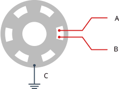
Rotary Encoder Operation: Rotary encoders operate by establishing electrical connections as a knob is turned. Two pins, labeled A and B, make contact with a common ground pin, marked as C, in a specific sequence determined by the direction of knob rotation.
Quadrature Encoding: As the A and B pins touch the common ground, they produce signals that are 90 degrees out of phase with each other. This phenomenon is referred to as quadrature encoding, a fundamental concept in rotary encoder technology.
Directional Information: The direction in which the knob is turned can be deduced by observing the order in which A and B pins make contact with the ground. Here's how it works:
- When the knob is turned clockwise, the A pin connects to the ground before the B pin.
- Conversely, when the knob is turned counterclockwise, the B pin connects to the ground before the A pin.

Detecting Rotation: To determine the direction of rotation, one can monitor the timing of the connections and disconnections of each pin with the ground. A simple way to do this is by observing the state of the B pin when the A pin changes.

- If the state of B doesn't match that of A, it indicates a clockwise rotation.
Clockwise rotation of the rotary encoder output pulses
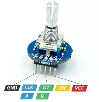
Pinout of the Module:
|
Pin Type |
Description |
|
S1-CLK |
Encoder Pin A |
|
S2-DT |
Encoder Pin B |
|
Key-SW |
push-button switch |
|
VCC(+) |
Voltage input(+5V) |
|
GND |
Ground(Encoder Pin C) |
Applications:
- Robotics: Rotary encoders play a crucial role in robotic systems, providing precise feedback on the position of robot joints and limbs. This feedback is essential for accurate movement control and navigation.
- Industrial Automation: In manufacturing and industrial settings, rotary encoders are used to monitor the position of conveyor belts, robotic arms, and other machinery. They ensure precise control and alignment of processes.
- CNC Machines: Computer Numerical Control (CNC) machines rely on rotary encoders to accurately position cutting tools and workpieces, enabling high-precision machining and milling operations.
- Automotive Systems: Rotary encoders are used in vehicle applications, such as in the position sensing of throttle and steering components. They contribute to safe and efficient vehicle operation.
- Consumer Electronics: These modules can be found in various consumer electronic devices, including computer mice, volume control knobs on audio equipment, and camera lenses for precise focusing.
- Medical Devices: In the medical field, rotary encoders are used in equipment like MRI machines and robotic surgical systems to ensure precise positioning and movement.
- Aviation and Aerospace: Rotary encoders are used in flight control systems, where accuracy and reliability are critical for aircraft control surfaces.
- Scientific Instruments: They are integral in laboratory and research equipment, providing accurate positioning for precision measurements and experiments.
- Printing and Packaging: Rotary encoders are used in printing machines and packaging equipment to control the movement and alignment of materials and printing heads.
- Gaming and Virtual Reality: In gaming peripherals and virtual reality devices, rotary encoders can be employed to provide precise and responsive control inputs.
Circuit:
Certainly, here's a more detailed explanation of the module's connections to the Arduino Board:
Connection to Arduino Board:
To integrate the rotary encoder module with an Arduino Board, it's crucial to establish the right connections. Here's a step-by-step guide:
-
Ground (GND) and VCC Connections:
- The Ground (GND) pin of the module should be connected to the Arduino Board's Ground (GND) pin. This connection ensures a common reference point for electrical potential.
- Similarly, the VCC (Voltage Common Collector) pin of the module must be linked to the Arduino Board's corresponding VCC or 5V pin. This provides the necessary operating voltage to power the module.
-
Signal Output (S1 and S2) Connections:
- The S1 and S2 Out pins on the rotary encoder module should be connected to digital input pins on the Arduino Board. For instance, you can connect S1 to digital pin 6 and S2 to digital pin 7 on the Arduino.

Library:
no library is needed.
Code:
This code monitors the state changes of a rotary encoder and uses these changes to determine the direction of rotation (clockwise or counterclockwise) and updates the position, which is then printed to the serial monitor. This allows you to track and use the encoder's position in various Arduino projects:
// Define the pins for the encoder
#define outputA 6
#define outputB 7

// Initialize variables to keep track of the encoder state
int counter = 0;          // To store the position
int aState;               // To store the current state of outputA
int aLastState;           // To store the previous state of outputA

void setup() {
  // Set the pins as inputs
  pinMode(outputA, INPUT);
  pinMode(outputB, INPUT);

  // Initialize the serial communication
  Serial.begin(9600);

  // Read the initial state of outputA
  aLastState = digitalRead(outputA);
}

void loop() {
  // Read the current state of outputA
  aState = digitalRead(outputA);

  // If the previous and current states of outputA are different, a pulse has occurred
  if (aState != aLastState) {
    // Check the state of outputB to determine the direction of rotation
    if (digitalRead(outputB) != aState) {
      counter++;  // Clockwise rotation
    } else {
      counter--;  // Counterclockwise rotation
    }

    // Print the current position to the serial monitor
    Serial.print("Position: ");
    Serial.println(counter);
  }

  // Update the previous state of outputA with the current state
  aLastState = aState;
}
-
Definitions and Initialization:
- It defines the pins for the rotary encoder -
outputAas pin 6 andoutputBas pin 7. - Initializes variables:
counterto keep track of the encoder's position.aStateto store the current state ofoutputA.aLastStateto store the previous state ofoutputA.
- It defines the pins for the rotary encoder -
-
Setup:
- In the
setupfunction:- It configures pins
outputAandoutputBas input pins. - Initiates serial communication with a baud rate of 9600.
- Reads and stores the initial state of
outputAinaLastState.
- It configures pins
- In the
-
Loop:
- In the
loopfunction:- Continuously reads the current state of
outputAand stores it inaState. - Check if the current state
aStateis different from the previous stateaLastState. This indicates a pulse or change in the encoder's position. - If a change is detected:
- It further checks the state
outputBto determine the direction of rotation. IfoutputBis in a different state from, it's considered clockwise rotation, and thecounteris incremented. Otherwise, it's counterclockwise, and thecounteris decremented. - It then prints the current position (stored in
counter) to the serial monitor, indicating the encoder's relative position.
- It further checks the state
- Finally, it updates
aLastStatewith the current stateaStateto prepare for the next iteration.
- Continuously reads the current state of
- In the
Technical Details:
- Operating Voltage: 5V
- Mechanical angle: 360 Degrees
- Output: 2-bit gray code
- Positions per revolution: 20
Resources:
Comparisons:
Rotary encoders and potentiometers serve similar purposes but have distinct characteristics, rotary encoders provide digital, continuous rotation for tracking changes in position, while potentiometers offer analog, limited rotation for precise and fixed knob positions:
- Offer a digital interface for position sensing.
- Rotate a full 360° without stopping.
- Ideal for applications that require tracking changes in position.
- Used when precise position is not crucial, but relative movement matters.
- Commonly employed for tasks like measuring speed and direction.
Potentiometers:
- Analog devices used for precise position control.
- Typically rotate only 3/4 of a circle.
- Valuable when an exact knob position is needed.
- Useful in scenarios where accurate and fixed settings are required, such as volume controls.