AED 16.00
Description
The Logic Level Converter Bi-Directional Module is a device that converts signals between devices operating at different voltage levels (5V to 3.3V and vice versa). It is bi-directional and compatible with 2.8V and 1.8V devices. The level converter allows for setting high and low voltage levels and converting signals between them on the same channel. It features 8 channels with two inputs and two outputs per side, making it efficient for various electronic projects.
Package Includes:
- 1 x Logic Level Converter Bi-Directional Module 8 Channel I2C 5V to 3.3V Red
Features:
- Bi-directional conversion: It can step down 5V signals to 3.3V and step up 3.3V signals to 5V.
- Compatibility: It works with a wide range of devices operating at different voltage levels including 2.8V and 1.8V.
- Voltage level customization: The high and low voltage levels can be set by the user.
- Safe conversion: The level converter converts signals between high and low voltage levels safely on the same channel.
- 8 channels: The module features 8 channels, each with two inputs and two outputs for each side.
- I2C interface: It uses I2C for communication, making it easy to integrate with other devices.
- Red color: The level converter has a red color, making it easily identifiable in electronic projects.
Description:
The Logic Level Converter Bi-Directional Module 8 channel I2C 5V to 3.3V Red is an essential tool for any electronic project that involves the integration of devices operating at different voltage levels. This bi-directional converter not only steps down 5V signals to 3.3V but also steps up 3.3V signals to 5V, making it compatible with a wide range of devices operating at different voltages, including 2.8V and 1.8V. With this level converter, you can set your high and low voltage levels and safely convert signals between them on the same channel, ensuring seamless communication between different devices. This 8-channel I2C level converter features two inputs and two outputs for each side, making it an efficient solution for a wide range of electronic projects. gearbox length of 24mm.
Principle of Work:
The Logic Level Converter Bi-Directional Module works on the principle of voltage level shifting. It allows signals from a device operating at one voltage level (e.g. 5V) to be transmitted to a device operating at a different voltage level (e.g. 3.3V) without damaging either device. The module contains an array of voltage-level shifters, one for each channel. When a signal is received on the high-voltage side, the shifter circuit adjusts the voltage level to match the low-voltage side. Conversely, when a signal is received on the low-voltage side, the shifter circuit adjusts the voltage level to match the high-voltage side. This allows for bi-directional communication between devices operating at different voltage levels.
The level shifters in the module are designed to provide a high level of electrical isolation between the high voltage side and the low voltage side, ensuring that the low voltage device is protected from any high voltage transients or surges that may be present on the high voltage side. Additionally, the level shifters are designed to provide a very fast transition time, ensuring that there is no degradation of signal quality or speed during the voltage level shift process.
Pinout of the Module:
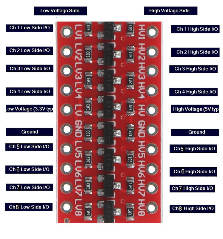
- High Voltage Side Pins (HV1, HV2, HV3, HV4, HV5, HV6, HV7, HV8): These pins are used to connect to the high voltage side of the system, which typically operates at a voltage level of 5V.
- Low Voltage Side Pins (LV1, LV2, LV3, LV4, LV5, LV6, LV7, LV8): These pins are used to connect to the low voltage side of the system, which typically operates at a voltage level of 3.3V.
- Ground Pin (GND): This pin is used to connect the module to the ground (GND) of the system.
- VCC H and L (HV-LV )Pin (VCC): This pin is used to provide power to the module. voltage sides with high and low voltage connect 3.3to LV and 5v to HV
Applications:
- Interfacing microcontrollers, sensors, and other devices operating at different voltage levels.
- Upgrading or replacing older electronics that use different voltage levels with newer ones.
- Converting voltage levels for I2C communication between devices operating at different voltage levels.
- Protecting low voltage devices from high voltage signals.
- Debugging and testing systems that use different voltage levels.
- Converting voltage levels for digital signals such as those used in communication protocols like SPI, UART, or I2C.
- Converting voltage levels for analog signals like those used in ADC or DAC circuits.
Circuit:
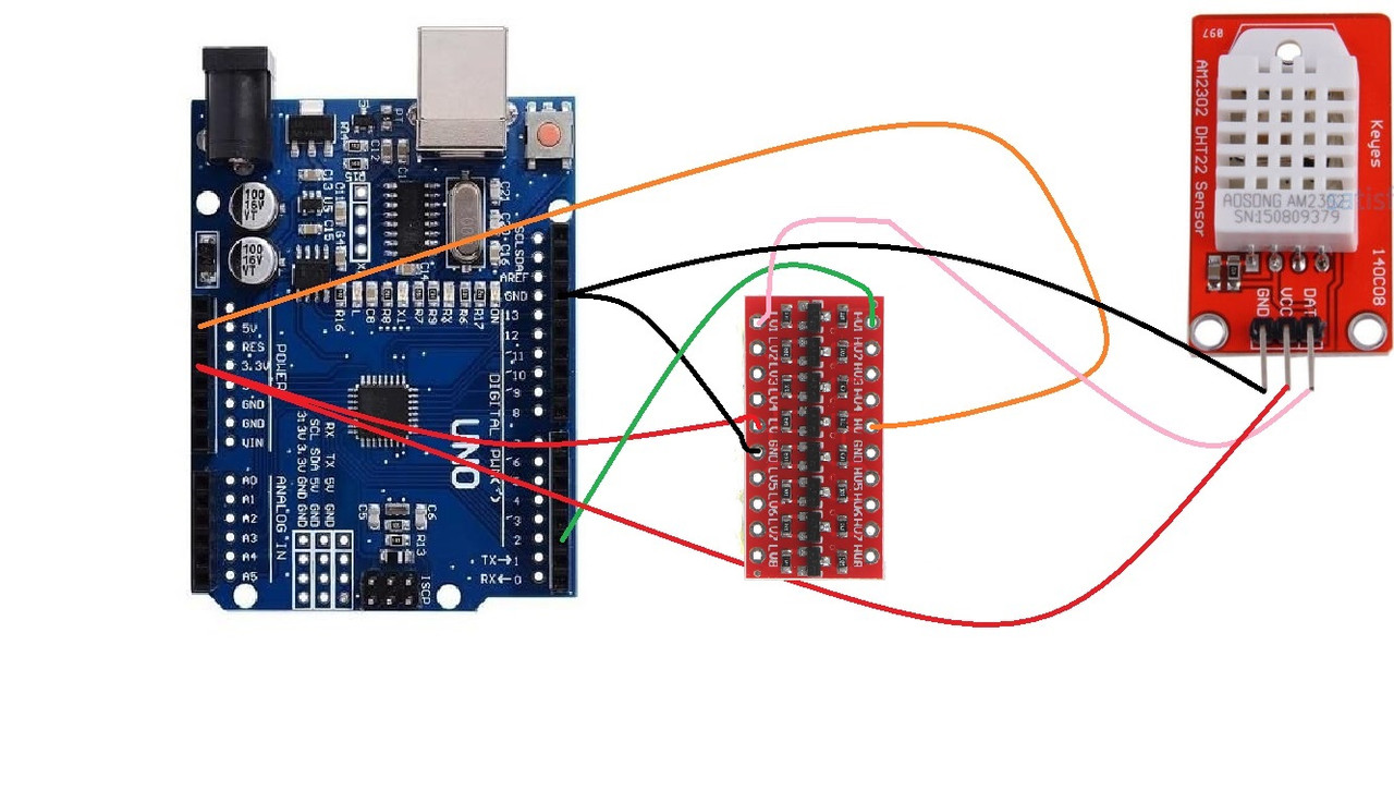
Example of how to use the Logic Level Converter Bi-Directional Module 4 Channel 5V to 3.3V in a circuit with a 3.3V DHT22 temperature and humidity sensor:
The connections would be as follows:
- Connect the LV (Low Voltage) pin to the 3.3V pin on the Arduino board.
- Connect the HV (High Voltage) pin to the 5V pin on the Arduino board.
- Connect the GND pin to the ground pin on the Arduino board.
- Connect the high-side input for channel 1 (H1) to the digital output pin on the Arduino board that you want to use to communicate with the DHT22 sensor.
- Connect the low-side input for channel 1 (L1) to the data pin on the DHT22 sensor.
With these connections in place, the signals from the Arduino board will be converted from 5V to 3.3V before being sent to the DHT22 sensor, allowing it to communicate with the sensor and receive data from it. Conversely, signals from the DHT22 sensor will be converted from 3.3V to 5V before being received by the Arduino, allowing it to understand the signal from the sensor.
Library:
To install the DHT library for use with an Arduino board, follow these steps:
- Open the Arduino IDE
- Go to
Sketch>Include Library>Manage Libraries - In the Library Manager search for "DHT sensor library"
- Find the
DHT sensor libraryby Adafruit and click on it - Click the "Install" button to install the library
- Close the Library Manager
- Restart the Arduino IDE if necessary
Code:
In this example, the DHT22 sensor is connected to digital pin 2 on the Arduino board. The DHT library is used to communicate with the sensor and read the temperature and humidity data. The data is then printed to the serial monitor in the Arduino IDE, allowing you to see the temperature and humidity readings in real time..
  #include "DHT.h"
#define DHTPIN 2     // Digital pin connected to the DHT sensor
#define DHTTYPE DHT22   // DHT 22  (AM2302)
DHT dht(DHTPIN, DHTTYPE);

void setup() {
  Serial.begin(9600);
  dht.begin();
}

void loop() {
  float h = dht.readHumidity();
  float t = dht.readTemperature();

  if (isnan(h) || isnan(t)) {
    Serial.println("Failed to read from DHT sensor!");
    return;
  }

  Serial.print("Humidity: ");
  Serial.print(h);
  Serial.print(" %\t");
  Serial.print("Temperature: ");
  Serial.print(t);
  Serial.println(" *C");

  delay(2000);
}
The code sets pin 9 on the Arduino board as the output pin for the motor, using the following line: const int motorPin = 9;.
In the setup() function, the pin mode of motorPin is set to OUTPUT using pinMode(motorPin, OUTPUT);, and serial communication is initialized with Serial.begin(9600).
The loop() the function contains the main code that will run repeatedly. It uses the analogWrite() function to turn the motor on (full speed) for onTime milliseconds and then turn the motor off for offTime milliseconds. The analogWrite() the function takes two arguments: the pin number and a value between 0 and 255 that represents the duty cycle of the PWM signal applied to the pin. A value of 255 means 100% duty cycle, which means the pin is on for the full period of the PWM signal.
There are two other functions in the code: speedUpandDown() and serialSpeed(). speedUpandDown() increases the motor speed from 0 to 255 and then decreases it back to 0 in increments of 20 milliseconds using a for loop. serialSpeed() allows you to set the motor speed by entering a value between 0 and 255 into the serial monitor of the Arduino software. The function Serial.parseInt() is used to read the value entered in the serial monitor and constrain() is used to ensure that the speed value is within the range of 0 to 255. The speed value is then passed to the analogWrite() function to set the speed of the motor.
Technical Details:
- Operating Voltage: 5V and 3.3V
- Input Voltage Range: 4.5V to 5.5V on the high voltage side and 2.7V to 3.6V on the low voltage side
- Channel Quantity: 8 channels
- Output Voltage Range: 0V to 3.3V on the low voltage side and 0V to 5V on the high voltage side
- Output Current: Depends on the input voltage, output voltage, and other conditions. Consult the datasheet for specific information.
- Operating Temperature Range: Typically -40°C to 85°C
- Size: 28x19mm / 1.1x0.74 inch
Resources:
Comparisons:
The Logic Level Converter Bi-Directional Module and a voltage divider circuit both serve the purpose of converting between high voltage and low voltage levels. However, they do so in different ways.
The Logic Level Converter Bi-Directional Module uses a specialized IC that is specifically designed to handle the level conversion between high and low voltage levels. This provides several advantages over a voltage divider circuit:
- Voltage Clamping: The Logic Level Converter protects the low-voltage side of the circuit by clamping the high voltage to a safe level, ensuring that the low-voltage devices are not damaged.
- Bidirectional Operation: The Logic Level Converter can convert signals in both directions, from high voltage to low voltage and vice versa, whereas a voltage divider circuit can only convert from high voltage to low voltage.
- Low Power Consumption: The Logic Level Converter consumes very little power, whereas a voltage divider circuit will consume more power due to the presence of resistors.
- Improved Signal Integrity: The Logic Level Converter provides improved signal integrity compared to a voltage divider circuit, as the IC is designed to minimize the impact of noise and other interference on the signal.
In conclusion, the Logic Level Converter Bi-Directional Module is a more specialized and advanced solution for level shifting compared to a voltage divider circuit. It offers several advantages over a voltage divider circuit, such as better protection, bidirectional operation, low power consumption, and improved signal integrity.