TheTIP120is an NPN Darlington Power Transistor. It can switch loads up to 60V with a peak current of 8A and a continuous current of 5A. This makes it suitable for medium and high power electronics like controlling motors, solenoids, or high power LEDs.
AED 4.20
Description
The TIP120 is an NPN Darlington Power Transistor designed for general-purpose amplifiers and low-speed switching applications. It consists of two NPN transistor stages connected in series, which provide a high DC current gain and low saturation voltage. The TIP120 can handle a maximum collector-emitter voltage of 60V and a continuous collector current of up to 5A. It is commonly used in motor control, solenoid drivers, and high-current LED drivers.
Package Includes:
- 1 x TIP120 NPN Darlington Power Transistor
Features:
- High DC current gain: The TIP120 has a high DC current gain, which means it can amplify a small base current into a larger collector current.
- High collector-emitter voltage: The TIP120 has a high collector-emitter voltage rating of 60V, making it suitable for high-voltage applications.
- High collector current: The TIP120 can handle a collector current of up to 5A, making it suitable for high-current applications.
- Darlington configuration: The TIP120 is designed in a Darlington configuration, which provides a very high current gain and low base current requirements.
- TO-220 package: The TIP120 is available in a TO-220 package, which makes it easy to mount on a heat sink.
- Fast switching: The TIP120 has a fast switching speed, which makes it suitable for switching applications.
- Low saturation voltage: The TIP120 has a low saturation voltage, which means it can operate with low power dissipation.
- Wide operating temperature range: The TIP120 can operate over a wide temperature range, from -65°C to 150°C.
Description:
The TIP120 is a popular NPN Darlington Power Transistor used in a wide range of electronic applications. It is designed for use as a general-purpose amplifier and low-speed switching device. It consists of two NPN transistor stages that are connected in series to provide high DC current gain and low saturation voltage. The TIP120 can handle a maximum collector-emitter voltage of 60V and a continuous collector current of up to 5A, making it suitable for a wide range of applications. One of the key advantages of the TIP120 is its high gain, which makes it suitable for use in high-current applications. The Darlington configuration provides a very high current gain, which makes it possible to drive a load with a relatively low input current. This can be especially useful in applications where the load requires a high current to operate, such as solenoid drivers and motor control circuits. Another advantage of the TIP120 is its low saturation voltage, which makes it possible to switch the transistor on and off with a relatively low voltage. This can be especially useful in applications where power dissipation is a concern, such as LED drivers. The TIP120 can handle a continuous collector current of up to 5A, which makes it suitable for driving high-current loads such as motors, solenoids, and LED arrays.
Principle of Work:
The TIP120 is an NPN Darlington transistor that can handle high current and voltage loads. It consists of two NPN transistors connected in a Darlington configuration, which provides a very high current gain. The base of the first NPN transistor is connected to the input signal and the base of the second NPN transistor is connected to the collector of the first transistor. The emitter of the second transistor is the output. When a current flows into the base of the first transistor, it turns on and allows current to flow through its collector to the base of the second transistor. This turns on the second transistor, which allows a large amount of current to flow through its emitter to the load. The TIP120 can be used as a switch or as an amplifier. When used as a switch, the transistor is either fully on or fully off, depending on the input signal. When used as an amplifier, the transistor amplifies the input signal by controlling the amount of current flowing through the load. The TIP120 requires a base current of around 5mA to turn on fully. This can be achieved by connecting the base to an Arduino digital output pin through a resistor. The collector of the transistor is connected to the positive power supply and the emitter is connected to the load.
Pinout of the Module:
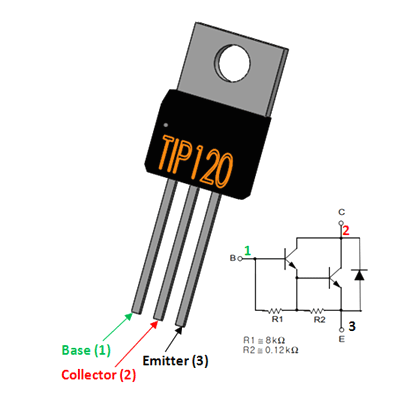
- Base (B): This is the pin that controls the flow of current through the transistor. It is the input pin and is used to turn the transistor on and off.
- Collector (C): This is the output pin that allows current to flow through the transistor when it is turned on.
- Emitter (E): This is the ground pin that allows current to flow out of the transistor when it is turned on.
Applications:
- Motor control: The TIP120 can be used to control the speed and direction of DC motors. By varying the current to the motor through the transistor, the speed and direction can be controlled.
- Relay control: The TIP120 can be used to control the activation of relays. By connecting the relay coil to the collector and the emitter, the TIP120 can be used to switch the relay on and off.
- LED control: The TIP120 can be used to control the brightness of LEDs. By varying the current to the LED through the transistor, the brightness can be controlled.
- Audio amplification: The TIP120 can be used as an audio amplifier. By controlling the current through the transistor with an audio signal, the signal can be amplified and output through a speaker.
- Power switching: The TIP120 can be used to switch high-power devices on and off. By controlling the current through the transistor, it can be used to switch power to devices such as heaters, pumps, and solenoids.
Circuit:
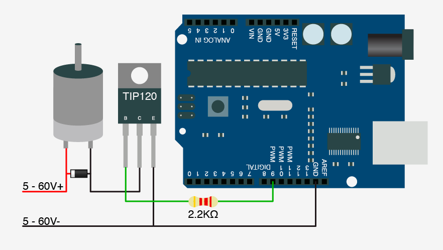
Connect a motor to the transistor as you see in the image and the voltage can be between 5 to 60 depending on the motor you use the base of the transistor is connected to Arduino pin 9 through a 2.2k resistor and between the motor legs you need to use a diode as a flyback diode to protect the transistor from the motor spikes
Library:
No Library was used
Code:
Example code in Arduino IDE demonstrates how to control a motor using a serial connection on pin 9:
int motorPin = 9; // Define the pin the motor is connected to
int speed = 0; // Initialize the speed to 0

void setup() {
  pinMode(motorPin, OUTPUT); // Set the motor pin to be an output
  Serial.begin(9600); // Initialize serial communication at 9600 baud
}

void loop() {
  if (Serial.available() > 0) { // Check if data is available on the serial port
    speed = Serial.parseInt(); // Read the integer value sent over serial and store it in the speed variable
    speed = map(speed, 0, 100, 0, 255); // Map the value from 0-100 to 0-255 to control the motor speed
    analogWrite(motorPin, speed); // Set the motor speed using PWM
  }
}
- we define
motorPinas the pin number that the motor is connected to (in this case, pin 10), and we initialize thespeedvariable to 0. In thesetup()function, we set the motor pin to be an output and initialize the serial communication at a baud rate of 9600. - In the
loop()function, we check if data is available on the serial port using theSerial.available()function. If there is data available, we read the integer value sent over serial using theSerial.parseInt()function and store it in thespeedvariable. We then map the value from 0-100 to 0-255 using themap()function, since theanalogWrite()function that we'll use to control the motor speed expects a value between 0 and 255. Finally, we set the motor speed using PWM using theanalogWrite()function, passing in themotorPinspeedvariables. - To control the motor from your computer, you can open the Serial Monitor in the Arduino IDE and send a value between 0 and 100. The code will map this value to a range between 0 and 255 and use it to control the motor speed.
Technical Details:
- NPN Medium-power Darlington Transistor
- High DC Current Gain (hFE), typically 1000
- Continuous Collector current (IC) is 5A
- Collector-Emitter voltage (VCE) is 60V
- Collector-Base voltage (VCB) is 60V
- Emitter Base Voltage (VBE) is 5V
- Base Current(IB) is 120mA
- The peak load current is 8A
- Available in To-220 Package
Resources:
Comparisons:
The TIP120 and IRFZ44NPBF are both power MOSFET transistors that can be used for switching and controlling high-current loads such as motors, solenoids, and LEDs. However, there are some differences between the two that may make one more suitable than the other depending on your application.
- Voltage rating: The TIP120 has a higher voltage rating of 60V compared to the IRFZ44NPBF's 55V. This means that the TIP120 can handle higher voltage loads and may be more suitable for applications that require higher voltage switching.
- Current rating: The IRFZ44NPBF has a higher current rating of 49A compared to the TIP120's 5A. This means that the IRFZ44NPBF can handle higher current loads and may be more suitable for applications that require higher current switching.
- Gate threshold voltage: The gate threshold voltage is the minimum voltage required to turn on the MOSFET. The IRFZ44NPBF has a lower gate threshold voltage of 2V compared to the TIP120's 2.5V. This means that the IRFZ44NPBF may be more suitable for applications where the gate voltage is limited.
- Base current: The TIP120 is a bipolar junction transistor (BJT) and requires a base current to turn on. The IRFZ44NPBF is a MOSFET and does not require a base current. This means that the IRFZ44NPBF may be easier to use in circuits where the available control signal is a voltage rather than a current.
- Heat dissipation: The IRFZ44NPBF has a lower on-resistance (RDS(on)) than the TIP120, which means it dissipates less heat when conducting current. This can make the IRFZ44NPBF more suitable for high-current applications where heat dissipation is a concern.
The TIP120 may be more suitable for applications that require higher voltage switching, while the IRFZ44NPBF may be more suitable for applications that require higher current switching and where the gate voltage is limited. Additionally, the IRFZ44NPBF may be easier to use in circuits where the control signal is a voltage rather than a current, and it may also dissipate less heat when conducting current. Ultimately, the choice between the two will depend on the specific requirements of your application.