AED 14.50
Description
The L293 exceptional quadruple high-current half-H drivers are designed to empower your electronic projects with seamless motor control capabilities. Whether you're driving relays, solenoids, DC motors, bipolar stepping motors, or other high-current/high-voltage loads in positive-supply applications, these devices are engineered for the task. The L293 offers bidirectional drive currents of up to 1 A at voltages ranging from 4.5 V to 25 V, while the L293D provides bidirectional drive currents of up to 600 mA within the same voltage range. Both devices are ideal for switching applications with frequencies up to 5 kHz.
Package Includes:
- 1 x Motor Driver Module 2ch 0.6A 25V L293D
Features:
- High Current Capacity: The L293 offers a good bidirectional drive currents, with the L293 supporting up to 1 A and the L293D up to 600 mA, ensuring reliable control of various loads.
- Wide Voltage Range: Both devices are designed to operate at voltages ranging from 4.5 V to 25 V, providing versatility for different electronic applications.
- Inductive Load Compatibility: Tailored for driving inductive loads such as relays, solenoids, DC motors, bipolar stepping motors, and other high-current/high-voltage loads in positive-supply scenarios.
- Switching Application Capability: Suitable for switching applications at frequencies up to 5 kHz, making them adaptable to a variety of electronic projects.
- Overtemperature Protection: The devices incorporate overtemperature protection, enhancing the durability and reliability of your motor control setup.
- Enable Facility: The enable facility feature adds flexibility to control the device's output, allowing for efficient power management in your projects.
- Noise-Resistant Operation: The logical "0" input voltage is supported up to 1.5V, ensuring high noise immunity for stable and interference-free performance.
- Internal Clamp Diodes: Equipped with internal clamp diodes to protect the circuit from voltage spikes and ensure the safety of connected components.
Description:
The L293D offers advanced capabilities for bidirectional motion and precise speed regulation of DC motors. Its intricately designed 16-pin configuration, evenly distributed with 8 pins on each side, empowers the independent and nuanced control of two DC motors. Positioned at the forefront of applications spanning from robotics to automation, the L293D operates on the ingenious principle of a dual H-bridge circuit, simplifying the intricate task of altering polarity across interconnected loads. With a voltage range spanning 4.5V to 36V, the L293D finds its place in a spectrum of motor setups, ensuring adaptability and flexibility. Noteworthy features like overtemperature protection enhance reliability in demanding scenarios. The IC’s ability to handle a maximum peak motor current of 1.2A and a continuous motor current of 600mA underscores its suitability for diverse high-current applications. This dynamic motor driver IC, with its sophisticated features and robust design, remains a cornerstone for engineers and hobbyists alike, driving innovation in various electronic projects.
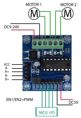
Principle of Work:
- The L293D motor driver module operates using a dual H-bridge configuration. The H-bridge is a circuit that allows the motor to be driven in both directions (forward and reverse) by controlling the polarity of the applied voltage. The L293D consists of two such H-bridge circuits, enabling the independent control of two DC motors. Each H-bridge consists of four transistors arranged in a specific way to facilitate bidirectional motor control.
- When using the L293D with a microcontroller (MCU), such as Arduino, the MCU sends digital signals to the input pins of the L293D, specifying the desired motor operation. The input pins control the state of the H-bridge, determining the direction and speed of the connected motors. By toggling these input signals, the MCU can regulate the motor's rotation and easily switch between forward, reverse, and braking states.
- The Enable pins on the L293D, such as Enable 1,2 and Enable 3,4, allow the MCU to activate or deactivate the corresponding H-bridge, providing a convenient way to enable or disable motor channels. Additionally, the L293D can handle external signals from sensors or other control devices to integrate more complex motor control strategies into the system.
Pinout of the Module:
| Pin Number | Pin Name | Description |
|---|---|---|
| 1 | Enable 1,2 | This pin enables Input 1(2) and Input 2(7). Connected to a digital circuit or controller, when set to HIGH, it allows the input pins to control the corresponding output pins. |
| 2 | Input 1 | Directly connected to Output 1 pin. Controlled by digital circuits or a microcontroller. When set to HIGH, it activates Output 1 pin, and vice versa. |
| 3 | Output 1 | Connected to one end of Motor 1. Controlled by Input 1 pin, when set to HIGH, it turns on Motor 1, and vice versa. |
| 4 | Ground | Ground pins are connected to the ground of the circuit (0V). They serve as a reference point for all voltage measurements and ensure the circuit is properly grounded. |
| 5 | Ground | Ground pins are connected to the ground of the circuit (0V). They serve as a reference point for all voltage measurements and ensure the circuit is properly grounded. |
| 6 | Output 2 | Connected to the other end of Motor 1. Controlled by Input 2 pin, when set to HIGH, it turns on Motor 1, and vice versa. |
| 7 | Input 2 | Directly connected to Output 2 pin. Controlled by digital circuits or a microcontroller. When set to HIGH, it activates Output 2 pin, and vice versa. |
| 8 | Vcc2 (Vs) | Connected to the voltage source for running the motors (4.5V to 36V). Provides the necessary voltage for the motors to operate. |
| 9 | Enable 3,4 | This pin enables Input 3(10) and Input 4(15). Connected to a digital circuit or controller, when set to HIGH, it allows the input pins to control the corresponding output pins. |
| 10 | Input 3 | Directly connected to Output 3 pin. Controlled by digital circuits or a microcontroller. When set to HIGH, it activates Output 3 pin, and vice versa. |
| 11 | Output 3 | Connected to one end of Motor 2. Controlled by Input 3 pin, when set to HIGH, it turns on Motor 2, and vice versa. |
| 12 | Ground | Ground pins are connected to the ground of the circuit (0V). They serve as a reference point for all voltage measurements and ensure the circuit is properly grounded. |
| 13 | Ground | Ground pins are connected to the ground of the circuit (0V). They serve as a reference point for all voltage measurements and ensure the circuit is properly grounded. |
| 14 | Output 4 | This pin is connected to the other end of Motor 2. It is controlled by Input 4 pin and when set to HIGH, it turns on Motor 2 and vice versa. |
| 15 | Input 4 | This pin is directly connected to Output 4 pin. It is controlled by digital circuits or a microcontroller, and when set to HIGH, it turns on Output 4 pin and vice versa. |
| 16 | Vcc2 (Vss) | This pin is connected to +5V to enable the IC function. It provides the necessary power for the IC to operate properly. |
Applications:
-
Motor Control Module Applications: Robotics: The module can be employed in robotics for controlling the movement of robotic arms or wheels by managing the motors connected to Output 1 and Output 2. Automated Systems: Suitable for automation systems where precise motor control is essential, such as conveyor belts or automated production lines.
-
Industrial Automation: Machine Control: Used in industrial machinery control, where the module can enable/disable specific inputs to control the corresponding outputs, facilitating complex automation processes.
-
Electronic Systems with Voltage Regulation: Motor Voltage Control: The Vcc2 (Vs) pins provide a voltage source for running motors, making the module applicable in systems requiring controlled motor speeds or torque.
-
Microcontroller-Based Systems: Digital Circuit Integration: Ideal for integration into microcontroller-based systems, enabling digital control over various outputs based on the state of corresponding input pins.
-
Electronic Circuit Grounding: Circuit Grounding: The ground pins serve as reference points for voltage measurements, ensuring proper grounding in electronic circuits to maintain signal integrity.
-
Multimotor Control Systems: Multimotor Applications: Well-suited for systems requiring control over multiple motors, as indicated by Output 1, Output 2, Output 3, and Output 4 connections.
-
Power Supply Voltage Management: IC Functionality: The Vcc2 (Vss) pin, connected to +5V, enables the IC function, making the module applicable in scenarios where precise power supply voltage management is necessary.
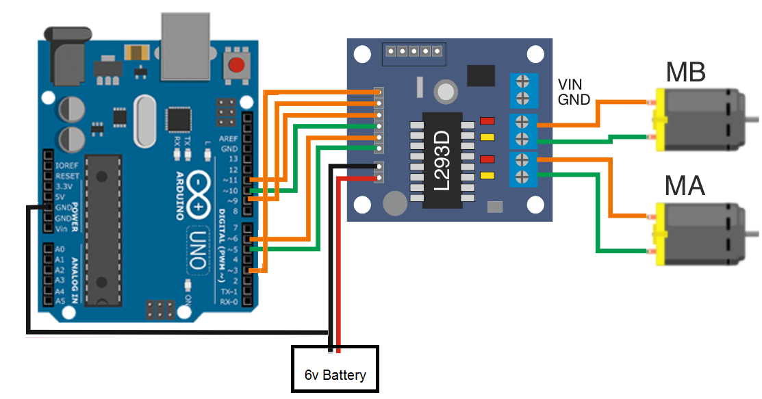
Circuit:
Library:
No library is needed.
Code:
This Arduino code controls two DC motors using a motor control module, The loop repeats, causing the motors to move forward, pause, move backward, and pause again. The specific pins and motor control logic should be adjusted based on the actual motor control module used and the physical connections to the motors.
// Motor 1 connections
int motor1Input1 = 5;  // Connect to the Input 1 pin of Motor 1
int motor1Input2 = 6;  // Connect to the Input 2 pin of Motor 1
int motor1Enable = 9;  // Connect to the Enable 1,2 pin of Motor 1

// Motor 2 connections
int motor2Input1 = 10;  // Connect to the Input 3 pin of Motor 2
int motor2Input2 = 11;  // Connect to the Input 4 pin of Motor 2
int motor2Enable = 3;   // Connect to the Enable 3,4 pin of Motor 2

void setup() {
  // Set the motor control pins as outputs
  pinMode(motor1Input1, OUTPUT);
  pinMode(motor1Input2, OUTPUT);
  pinMode(motor1Enable, OUTPUT);

  pinMode(motor2Input1, OUTPUT);
  pinMode(motor2Input2, OUTPUT);
  pinMode(motor2Enable, OUTPUT);
}

void loop() {
  // Motor 1: Move forward
  digitalWrite(motor1Input1, HIGH);
  digitalWrite(motor1Input2, LOW);
  analogWrite(motor1Enable, 255);  // Adjust the speed by changing the PWM value (0 to 255)

  // Motor 2: Move forward
  digitalWrite(motor2Input1, HIGH);
  digitalWrite(motor2Input2, LOW);
  analogWrite(motor2Enable, 255);  // Adjust the speed by changing the PWM value (0 to 255)

  delay(2000);  // Run motors forward for 2 seconds

  // Stop both motors
  digitalWrite(motor1Enable, LOW);
  digitalWrite(motor2Enable, LOW);

  delay(1000);  // Pause for 1 second

  // Motor 1: Move backward
  digitalWrite(motor1Input1, LOW);
  digitalWrite(motor1Input2, HIGH);
  analogWrite(motor1Enable, 255);  // Adjust the speed by changing the PWM value (0 to 255)

  // Motor 2: Move backward
  digitalWrite(motor2Input1, LOW);
  digitalWrite(motor2Input2, HIGH);
  analogWrite(motor2Enable, 255);  // Adjust the speed by changing the PWM value (0 to 255)

  delay(2000);  // Run motors backward for 2 seconds

  // Stop both motors
  digitalWrite(motor1Enable, LOW);
  digitalWrite(motor2Enable, LOW);

  delay(1000);  // Pause for 1 second
}
- Motor Connections: It defines the pins on the Arduino to which the motor control module is connected. The pins for Motor 1 are
motor1Input1,motor1Input2, andmotor1Enable. For Motor 2, the pins aremotor2Input1,motor2Input2, andmotor2Enable. - Setup Function: In the
setup()function, it sets the defined pins as OUTPUT, indicating that these pins will be used to output control signals to the motor control module. - Loop Function: The
loop()function contains the main control logic for the motors, and it runs continuously. -
Move Motors Forward:
- It sets the appropriate input signals (
HIGHandLOW) for both motors to make them move forward. The speed of the motors is controlled by theanalogWritefunction applied to the enable pins (motor1Enableandmotor2Enable). In this case, the speed is set to the maximum value of 255. - After running the motors forward for 2 seconds, it stops both motors by setting the enable pins to
LOW.
- It sets the appropriate input signals (
- Pause: It pauses for 1 second using the
delay(1000)function. - Move Motors Backward:
- It sets the input signals for both motors to make them move backward. The speed is controlled similarly to the forward motion.
- After running the motors backward for 2 seconds, it stops both motors.
-
Final Pause: It pauses for 1 second again.
Technical Details:
- Input Voltage Range: DC 4.5V to 25V
- Output Current Capability: 600mA per channel
- Peak Output Current: 1.2A (non-repetitive) per channel
- Enable Facility: Yes
- Overtemperature Protection: Yes
- Logical "0" Input Voltage: Up to 1.5V
- Switching Frequency: Up to 5 kHz
Resources:
Comparisons:
Using a motor control module, such as the one described in your code, offers several advantages compared to using the bare-bone L293D motor driver. Here are some points of comparison:
Motor Control Module:
- Ease of Use: Motor control modules often come with pre-designed circuitry and connectors, making them easier to integrate into a project without needing extensive knowledge of motor control electronics.
- Pin Simplification: Modules typically use fewer pins on the microcontroller as they incorporate features like PWM speed control and direction control, simplifying the wiring and code.
- Built-in Protections: Many motor control modules include built-in features such as overcurrent protection, preventing damage to the motors and the module itself.
- Compact Design: Motor control modules are usually compact and integrate multiple components, saving space on a project and reducing the overall complexity of the circuit.
- Ease of Scaling: When expanding a project with additional motors, using modules is often simpler as they can be easily connected in parallel or series.
Bare-bone L293D:
- Customization: Using the L293D without a module allows for more customization. Developers have more control over the circuit design and can tailor it to specific project requirements.
- Educational Purposes: Working with the L293D directly can be valuable for educational purposes, providing a deeper understanding of motor control concepts and electronic circuits.
- Cost: The L293D is a relatively inexpensive IC, which might be an advantage in projects with strict budget constraints.
- Flexibility: Using the L293D allows for greater flexibility in terms of power supply voltage and current requirements, as it can handle a variety of motors within its specified limits.
Considerations:
-
Complexity vs. Simplicity:
- If simplicity and ease of use are crucial, a motor control module is often a better choice.
- If customization and in-depth understanding of the motor control circuit are priorities, using the L293D directly may be preferred.
- Project Requirements: Consider the specific needs of your project. If the features offered by a motor control module meet your requirements, it may be the more practical choice.
- Learning Goals: If the project is for educational purposes and you want to learn more about motor control circuits, using the bare-bone L293D can be a valuable learning experience.