AED 14.95
Description
This LED matrix module is a versatile display unit that allows users to create dynamic visual content with ease.
Specifications:
- Drive Capability: A single module has the capacity to drive an 8 x 8 common cathode lattice, providing a total of 64 individually addressable LEDs.
- Operating Voltage: Designed to operate at a standard 5V, making it compatible with common microcontroller units (MCUs) and other electronic systems.
- Compact Size: The module is compact, measuring 5 x 3.2 x 1.5 cm (Length x Width x Height), allowing for efficient integration into various projects.
- LED Color: The LEDs emit a vibrant red color, adding visual appeal to the display.
- Mounting Convenience: Equipped with four screws holes, each with a 3mm aperture, facilitating easy and secure mounting in different applications.
- Cascading Capability: The module features input and output interfaces, supporting the cascading of multiple modules. This enables the creation of larger and more complex displays by connecting the output of one module to the input of another.
Wiring Instructions:
- The module has a designated input port on the left side and an output port on the right side.
- For controlling a single module, connect the input port to the Microcontroller Unit (MCU).
- When cascading multiple modules, connect the input port of the first module to the MCU, and then connect the output port of the first module to the input port of the second module. Repeat this process for additional modules in the cascade.
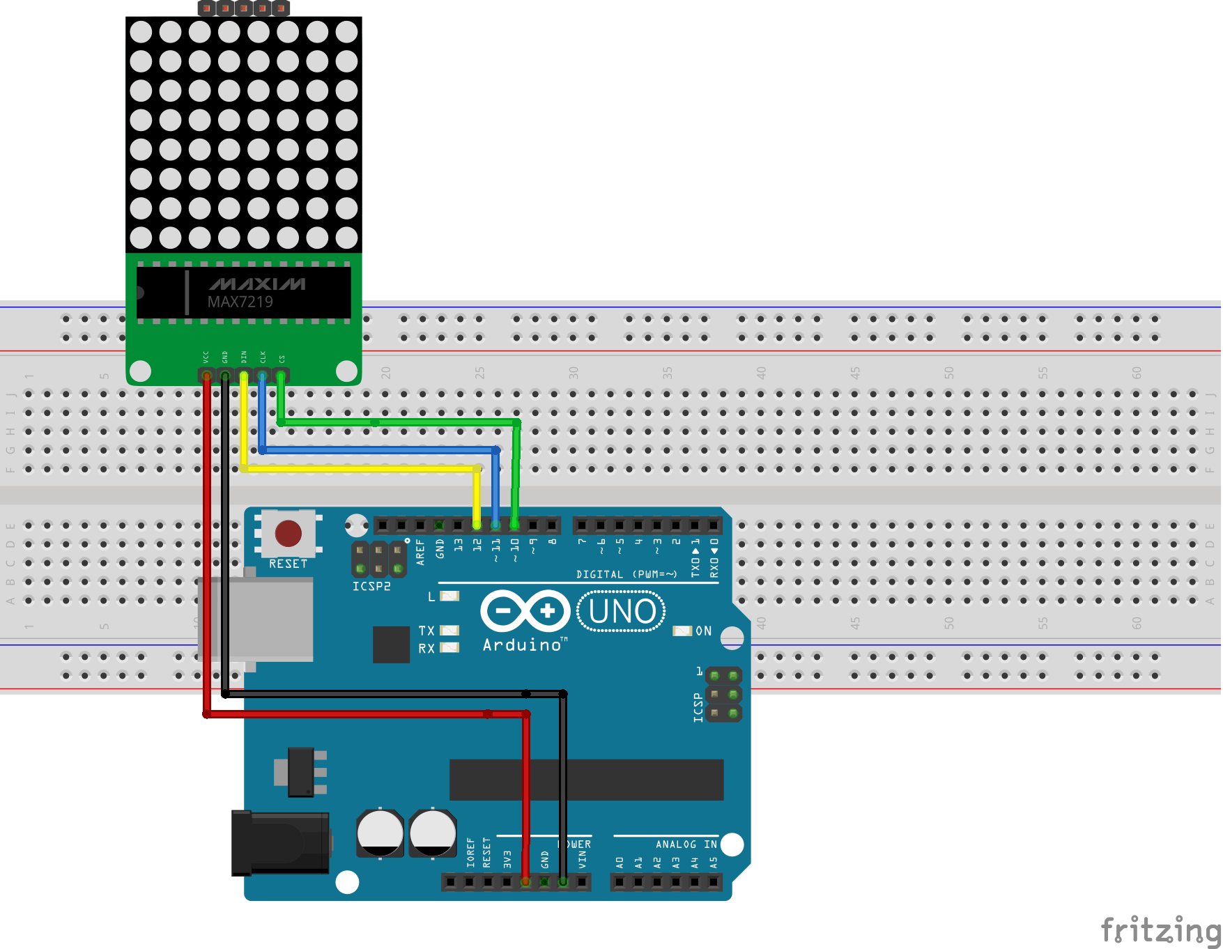
- Wiring With Arduino Uno:
- VCC → 5V
- GND → GND
- DIN → 12
- CS → 10
- CLK → 11
To visualize the setup and usage, refer to this YouTube video.
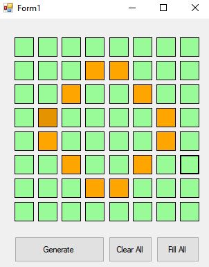
The 8×8 LED matrix comprises 64 LEDs, which can display graphics, text, and symbols by selectively turning specific LEDs on and off. Rather than manually creating a byte array for each display, a software tool called "pixeltomatrix" simplifies the process by generating byte arrays based on the designed graphics.
![]()
Creating Graphics: Graphics are designed by highlighting specific areas in the image, representing the desired display. An example of creating the character "O" is shown below:
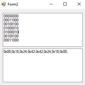
After highlighting, clicking the generate button in the software translates the marked pixels into a byte
array, such as the one shown below:
Code: The Arduino code for this project can be downloaded from the following link:
LED Matrix Arduino Code.
Libraries: The project requires the LED control library, which can be downloaded from https://github.com/wayoda/LedControl. Install the library by unzipping it into your Arduino Libraries folder.
Package Includes:
- 1 x 8x8 Matrix Red LEDs
- 1 x Board
- 1 x Cable for connecting