AED 36.75
Description
The Motor Driver Module 2A 2-Motors L298N RobotDYN is an electronic Module with an IC that can control the direction and speed of two DC motors simultaneously. It is designed for use in robotics projects and other applications that require precise motor control. The module uses the L298N dual H-bridge chip to provide high current and voltage capability to drive the motors. It supports a wide range of input voltages and can handle a maximum output current of 2A per channel. The module also includes a set of control pins that allow for easy interfacing with microcontrollers and other control circuits.
Package Includes:
- 1 x RobotDYN L298N Motor Driver Module 2A 2-Motors
Features:
- 400 tie-points Mini Breadboard: This breadboard has 400 tie-points, providing ample space for building and testing circuits.
- 2 Distribution Strips: The breadboard also features two distribution strips, which make it easy to connect power and ground to your circuit.
- Tie-point 100: In addition to the distribution strips, the breadboard also has a tie-point 100 area, which allows for more flexible circuit design.
- Size: The size of the breadboard is 3.5x8.2x0.85 (cm), making it compact and easy to store.
- Material: The breadboard is made from ABS, which is a durable and lightweight material.
- Match jumper, wire diameter 0.8mm: The breadboard is designed to work with jumper wires that have a diameter of 0.8mm, making it compatible with a wide range of electronic components.
Description:
The Motor Driver L298N for Arduino is an electronic module designed to control two DC motors. It allows the user to control the rotational speed and direction of the motors, as well as stop them with freewheeling or block their action altogether. The module is also capable of controlling a bipolar step motor with a maximum current of up to 4A. This motor driver module is based on the L298P chip, which can handle input voltages ranging from 5-36V and peak current up to 2A on each channel. The module has an LED that indicates the rotational direction of each motor. The user can switch between two modes of control (Direct control and Logic control) using the shield switches, with an individual switch provided for each channel. The Motor Driver L298N for Arduino is a versatile and powerful motor control module that can be used in a wide range of applications, including robotics and automation.
Principle of Work:
The Motor Driver L298N for Arduino is based on the L298P chip, which provides two H-bridges that can drive two DC motors simultaneously. The module allows the user to control the direction and speed of the motors through the Arduino microcontroller. The speed regulation is achieved through the Pulse Width Modulation (PWM) default mode. The module accepts a PWM signal from the Arduino outputs 10 and 11, which are digital outputs that comply with PWM. The PWM signal determines the rotational speed of the motors, with a higher duty cycle resulting in a higher speed. The module offers two modes of rotational control: Direct control and Logic control. In Direct control mode, the user can control each motor independently using three Arduino outputs for each channel. For Motor 1, these outputs are 8, 9, and 10(PWM), while for Motor 2, they are 11(PWM), 12, and 13. The user can apply a high signal to any of these outputs to drive the motor in a particular direction. In Logic control mode, the user can control both motors with just four digital outputs. For Motor 1, the user can apply a high signal to outputs 9 and 10(PWM), while for Motor 2, they can apply a high signal to outputs 11(PWM) and 13. The module provides free digital outputs 8 and 12, which can be used for other purposes. The user can switch between these two modes of control using the shield switches, with an individual switch provided for each channel.
Pinout of the Module:
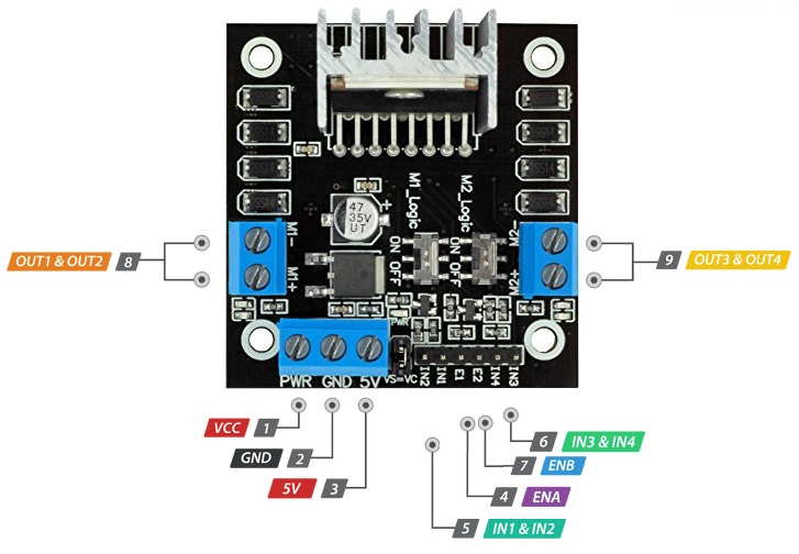
- 5V - Input voltage (5-35V)
- GND - Ground
- IN1 - Input 1 for Motor 1
- IN2 - Input 2 for Motor 1
- IN3 - Input 1 for Motor 2
- IN4 - Input 2 for Motor 2
- +5V - Provides 5V output to power the Arduino
- ENA - Enable A: PWM input for controlling the speed of Motor 1
- ENB - Enable B: PWM input for controlling the speed of Motor 2
- OUT1 - Output 1 for Motor 1
- OUT2 - Output 2 for Motor 1
- OUT3 - Output 1 for Motor 2
- OUT4 - Output 2 for Motor 2
- Direct/Logic switch - Switch to select Direct control or Logic control mode
- +12V - Output voltage (up to 2A) for an external power supply
- +5V - Output voltage (up to 2A) for an external power supply
- GND - Ground for an external power supply
Applications:
- Robotics: The module is commonly used in robotics projects to control the movement of wheels, arms, and other components. It can be used to control the direction and speed of two motors independently, allowing for precise control of movement.
- Motorized vehicles: The module can be used to control the movement of motorized vehicles such as remote-controlled cars, boats, and planes. It allows for precise control of the speed and direction of the motors, which is essential for accurate control of the vehicle.
- Industrial automation: The module can be used in industrial automation applications such as conveyor systems, assembly lines, and other processes that require precise control of motors.
- Home automation: The module can be used in home automation projects to control the movement of blinds, curtains, and other motorized components.
- DIY projects: The module can be used in a wide variety of DIY projects that require precise control of DC motors or bipolar stepper motors.
Circuit:
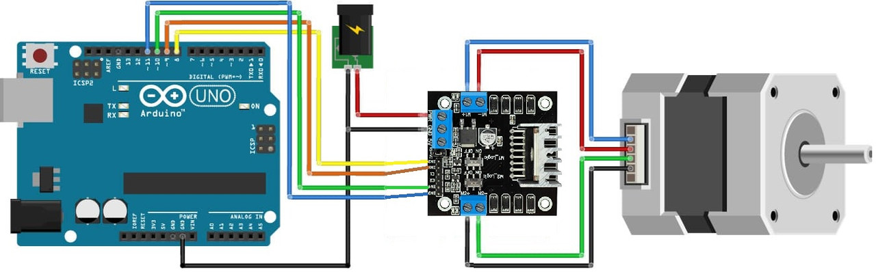
The circuit connections for the L298N module:
- +12V: Connect to a 5-35 V power supply.
- GND: Connect to the power supply and Arduino ground.
- 12 V jumper: Remove if motor power is greater than 12 V.
- 5V+ (optional): Connect to the 5 V output pin of the Arduino if the 12 V jumper is removed.
- IN1: Connect to pin 8 on the Arduino.
- IN2: Connect to pin 9 on the Arduino.
- IN3: Connect to pin 10 on the Arduino.
- IN4: Connect to pin 11 on the Arduino.
- ENA and ENB jumper: Leave installed.
- OUT1 + OUT2: Connect to the stepper motor coil A.
- OUT3 + OUT4: Connect to the stepper motor coil B.
Code:
A code to control a stepper motor using the L298N module and serial monitor:
To use this code, connect the L298N module to your Arduino board as described earlier. Then, upload the code to your Arduino board and open the serial monitor. Enter several steps (positive for clockwise and negative for counterclockwise) into the serial monitor and press enter. The stepper motor will move the specified number of steps in the specified direction.
// Include the required libraries
#include "Stepper.h"

// Define the stepper motor parameters
const int stepsPerRevolution = 200;  // change this to fit the number of steps per revolution
const int motorSpeed = 30;           // motor speed in RPM
Stepper myStepper(stepsPerRevolution, 8, 10, 9, 11); // IN1-IN4

void setup() {
  // Set up the serial monitor
  Serial.begin(9600);

  // Set the motor speed
  myStepper.setSpeed(motorSpeed);
}

void loop() {
  // Check if there is incoming data from the serial monitor
  if (Serial.available() > 0) {
    // Read the incoming data
    int steps = Serial.parseInt();

    // Move the motor
    if (steps != 0) {
      if (steps > 0) {
        Serial.print("Moving motor clockwise ");
      } else {
        Serial.print("Moving motor counterclockwise ");
        steps = abs(steps);
      }
      Serial.print(steps);
      Serial.println(" steps");
      myStepper.step(steps);
    }
  }
}
- First, we include the Stepper library which will allow us to control the stepper motor.
- Next, we define some parameters for the stepper motor.
stepsPerRevolutionis the number of steps the motor takes to complete one revolution, andmotorSpeedis the desired speed of the motor in revolutions per minute (RPM). We then create an instance of the Stepper class calledmyStepper, which takes four parameters: the number of steps per revolution, and the four pins (IN1, IN2, IN3, and IN4) connected to the L298N module. - In the
setup()function, we initialize the serial monitor with a baud rate of 9600 and set the speed of the stepper motor using thesetSpeed()method of themyStepperobject. - In the
loop()function, we check if there is any data available from the serial monitor using theSerial.available()method. - If there is data available, we read the incoming data using the
Serial.parseInt()method, which reads an integer value from the serial monitor. - We then check if the value
stepsis nonzero. If it is, we determine the direction of the motor based on whetherstepsis positive (clockwise) or negative (counterclockwise). Ifstepsis negative, we take its absolute value of it so that we can pass a positive value to themyStepper.step()method. - We then use the
Serial.print()andSerial.println()methods to output some text to the serial monitor indicating the direction and number of steps to be taken by the motor. - Finally, we call the
myStepper.step()method to move the motor the specified number of steps in the specified direction.
Technical Details:
- Operating Voltage: 5-35V DC
- Maximum output current: 2A per channel (4A peak)
- Logic supply voltage: 5V DC
- Built-in protection diodes for reverse polarity, overvoltage, and overtemperature
- Two modes of rotational control: Direct and Logic
- Speed control through PWM signal (via Arduino PWM pins)
- Supports driving bipolar stepper motors up to 4A current
- Can drive two DC motors or one stepper motor
- Built-in indicator LEDs for motor direction
Resources:
Comparisons:
comparison between L298N and L293D motor driver modules:
L298N:
- Higher operating voltage range (5-35V) compared to L293D (4.5-36V)
- Higher maximum output current (2A per channel) compared to L293D (0.6A per channel)
- Supports driving bipolar stepper motors up to 4A current, while L293D can drive unipolar stepper motors up to 1A current
- Built-in protection diodes for reverse polarity, overvoltage, and overtemperature
- Two modes of rotational control: Direct and Logic
- Supports speed control through PWM signal (via Arduino PWM pins)
- Built-in indicator LEDs for motor direction
L293D:
- Lower cost compared to L298N
- Smaller package and simpler pin configuration compared to L298N
- Can drive up to four DC motors or two stepper motors
- Can operate at a wider range of temperatures compared to L298N
L298N is a more powerful and versatile motor driver module, while L293D is a simpler and more affordable option suitable for less demanding projects.