AED 29.95
Description
The Ethernet Network Module W5500 USR-ES1 SPI is a small, compact module designed for embedded systems that require network communication capabilities. It features a high-speed SPI interface, a built-in TCP/IP protocol stack, and supports up to 8 independent sockets simultaneously. The module supports a range of network protocols, including TCP, UDP, ICMP, IPv4, ARP, IGMP, and PPPoE. It has an embedded Ethernet PHY and supports auto-negotiation for easy connectivity. The module also includes LED indicators for visual feedback on its operational status and a compact pin-type package for easy integration. It is an ideal solution for users who want to quickly and easily implement network communication in their embedded systems.
Package Includes:
- 1 x Ethernet Network Modules W5500 USR-ES1 SPI
Features:
- High-speed SPI interface: The module has a high-speed SPI interface with a clock speed of up to 80 MHz, which enables fast and efficient communication with the host microcontroller.
- Hardware TCP/IP protocol stack built-in: The module has an onboard TCP/IP protocol stack that allows the user to implement network communication without requiring an in-depth knowledge of complex network protocols.
- Supports up to 8 independent sockets simultaneously: The module can handle up to 8 separate sockets, which can be used to establish multiple connections at the same time.
- Supports TCP, UDP, ICMP, IPv4, ARP, IGMP, and PPPoE protocols: The module supports a range of network protocols, including TCP (Transmission Control Protocol), UDP (User Datagram Protocol), ICMP (Internet Control Message Protocol), IPv4 (Internet Protocol version 4), ARP (Address Resolution Protocol), IGMP (Internet Group Management Protocol), and PPPoE (Point-to-Point Protocol over Ethernet).
- Integrated data link layer and physical layer: The module integrates the data link layer and physical layer of the OSI model, making it easier to implement network communication in embedded systems.
- Supports wake-up function: The module supports a wake-up function that allows the module to be put into sleep mode to conserve power when it is not in use. When a data packet is received, the module will wake up and resume communication.
- Internal 32KB buffer for RX/TX: The module has an internal 32KB buffer for receiving and transmitting data, which helps to ensure smooth and uninterrupted network communication.
- Embedded 10BaseT/100BaseTX Ethernet physical layer (PHY): The module has an embedded Ethernet PHY, which allows it to connect to a 10BaseT or 100BaseTX Ethernet network.
- Supports auto-negotiation (10/100-Based full-duplex or half-duplex): The module supports auto-negotiation, which allows it to automatically detect and configure the appropriate network speed and duplex mode based on the connected device.
- LED indicators for full-duplex/half-duplex, network connection, network speed, and active status: The module has LED indicators that provide visual feedback on the module's operational status, including full-duplex/half-duplex mode, network connection, network speed, and active status.
Description:
The Ethernet Network Module W5500 USR-ES1 SPI is a compact and efficient module designed to provide network communication capabilities in embedded systems. It features a high-speed SPI interface that can communicate with a host microcontroller at speeds of up to 80 MHz, enabling fast and efficient data transfer. The module comes with a built-in TCP/IP protocol stack, which makes it easy for users to implement network communication without requiring a deep understanding of complex network protocols. This feature is particularly useful for embedded systems, where memory and processing power are often limited. One of the key advantages of the module is its ability to support up to 8 independent sockets simultaneously. This means that users can establish multiple network connections at the same time, making it ideal for applications that require concurrent data transfer. The module supports a range of network protocols, including TCP, UDP, ICMP, IPv4, ARP, IGMP, and PPPoE. This flexibility allows users to implement a wide range of network applications, from simple data transfer to more complex network functions. In addition to its protocol support, the module integrates the data link layer and physical layer of the OSI model, making it easier to implement network communication in embedded systems. It also supports a wake-up function, which enables the module to be put into sleep mode to conserve power when not in use and resume communication automatically when a data packet is received. The module includes an embedded 10BaseT/100BaseTX Ethernet physical layer (PHY), which allows it to connect to a 10BaseT or 100BaseTX Ethernet network. It supports auto-negotiation, which allows it to automatically detect and configure the appropriate network speed and duplex mode based on the connected device. The module also has LED indicators that provide visual feedback on its operational status, including full-duplex/half-duplex mode, network connection, network speed, and active status. This feature can be particularly useful for debugging and troubleshooting network connectivity issues.
Principle of Work:
- Hardware Connection: The module is connected to a host microcontroller via a high-speed SPI interface. The microcontroller sends commands and data to the module via the SPI interface, and the module responds with status and data packets.
- TCP/IP Protocol Stack: The module has a built-in TCP/IP protocol stack, which handles the complex network protocol functions. This includes tasks such as packet fragmentation and reassembly, error detection and correction, and network addressing.
- Socket Establishment: The module supports up to 8 independent sockets simultaneously, which allows users to establish multiple network connections at the same time. Users can configure the socket settings, including the IP address, port number, and protocol type, to establish a network connection.
- Data Transfer: Once a network connection is established, the module can transfer data between the embedded system and the network. The module supports a range of network protocols, including TCP, UDP, ICMP, IPv4, ARP, IGMP, and PPPoE, which allows users to implement a wide range of network applications.
- Power Management: The module supports a wake-up function, which enables it to be put into sleep mode to conserve power when not in use. When a data packet is received, the module automatically wakes up and resumes communication.
- Visual Feedback: The module includes LED indicators that provide visual feedback on its operational status, including full-duplex/half-duplex mode, network connection, network speed, and active status. This feature can be handy for debugging and troubleshooting network connectivity issues.
Pinout:
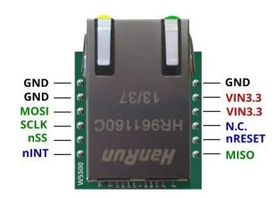
- GND - Ground
- VCC - Power Supply (3.3V DC)
- SCK - SPI Clock input
- MISO - SPI Master In Slave Out
- MOSI - SPI Master Out Slave In
- CS or SS - Chip Select for SPI communication
- RESET - Reset input
- INT - Interrupt output
Applications:
- Internet of Things (IoT): The module can be used in IoT applications to enable communication between sensors, controllers, and other IoT devices. This allows for remote monitoring and control of IoT devices and systems.
- Home Automation: The module can be used in home automation systems to control lighting, HVAC, security systems, and other home appliances via a network connection.
- Industrial Automation: The module can be used in industrial automation systems to enable communication between sensors, actuators, and controllers. This allows for real-time monitoring and control of industrial processes.
- Robotics: The module can be used in robotic systems to enable communication between robots, sensors, and controllers. This allows for remote control and monitoring of robots in real time.
- Medical Devices: The module can be used in medical devices to enable communication between medical equipment, patient monitoring devices, and other medical devices. This allows for remote monitoring and control of medical devices and systems.
- Automotive: The module can be used in automotive applications to enable communication between different components of the vehicle. This allows for remote monitoring and control of the vehicle's systems, such as engine and transmission control.
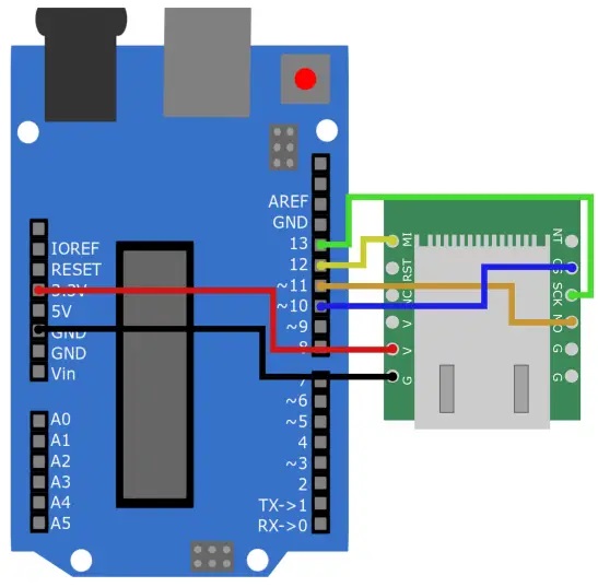
Circuit:
| Arduino |
Ethernet module |
|
3.3 V |
V |
|
GND |
G |
|
Pin 13 |
SCK |
|
Pin 12 |
MI |
|
Pin 11 |
MO |
|
Pin 10 |
CS |
Library:
No need to install any library the libraries are already installed.
Code:
This code demonstrates how to establish an Ethernet connection with an Arduino board and communicate with a web server over the Internet:
#include "SPI.h"
#include "Ethernet.h"

// Enter a MAC address for your controller below.
// Newer Ethernet shields have a MAC address printed on a sticker on the shield
byte mac[] = { 0xDE, 0xAD, 0xBE, 0xEF, 0xFE, 0xED };

// if you don't want to use DNS (and reduce your sketch size)
// use the numeric IP instead of the name for the server:
//IPAddress server(74,125,232,128);  // numeric IP for Google (no DNS)
char server[] = "www.google.com";    // name address for Google (using DNS)

// Set the static IP address to use if the DHCP fails to assign
IPAddress ip(192, 168, 0, 177);
IPAddress myDns(192, 168, 0, 1);

// Initialize the Ethernet client library
// with the IP address and port of the server
// that you want to connect to (port 80 is default for HTTP):
EthernetClient client;

// Variables to measure the speed
unsigned long beginMicros, endMicros;
unsigned long byteCount = 0;
bool printWebData = true;  // set to false for better speed measurement

void setup() {
  // You can use Ethernet.init(pin) to configure the CS pin
  //Ethernet.init(10);  // Most Arduino shields
  //Ethernet.init(5);   // MKR ETH shield
  //Ethernet.init(0);   // Teensy 2.0
  //Ethernet.init(20);  // Teensy++ 2.0
  //Ethernet.init(15);  // ESP8266 with Adafruit Featherwing Ethernet
  //Ethernet.init(33);  // ESP32 with Adafruit Featherwing Ethernet

  // Open serial communications and wait for port to open:
  Serial.begin(9600);
  while (!Serial) {
    ; // wait for serial port to connect. Needed for native USB port only
  }

  // start the Ethernet connection:
  Serial.println("Initialize Ethernet with DHCP:");
  if (Ethernet.begin(mac) == 0) {
    Serial.println("Failed to configure Ethernet using DHCP");
    // Check for Ethernet hardware present
    if (Ethernet.hardwareStatus() == EthernetNoHardware) {
      Serial.println("Ethernet shield was not found.  Sorry, can't run without hardware. :(");
      while (true) {
        delay(1); // do nothing, no point running without Ethernet hardware
      }
    }
    if (Ethernet.linkStatus() == LinkOFF) {
      Serial.println("Ethernet cable is not connected.");
    }
    // try to congifure using IP address instead of DHCP:
    Ethernet.begin(mac, ip, myDns);
  } else {
    Serial.print("  DHCP assigned IP ");
    Serial.println(Ethernet.localIP());
  }
  // give the Ethernet shield a second to initialize:
  delay(1000);
  Serial.print("connecting to ");
  Serial.print(server);
  Serial.println("...");

  // if you get a connection, report back via serial:
  if (client.connect(server, 80)) {
    Serial.print("connected to ");
    Serial.println(client.remoteIP());
    // Make a HTTP request:
    client.println("GET /search?q=arduino HTTP/1.1");
    client.println("Host: www.google.com");
    client.println("Connection: close");
    client.println();
  } else {
    // if you didn't get a connection to the server:
    Serial.println("connection failed");
  }
  beginMicros = micros();
}

void loop() {
  // if there are incoming bytes available
  // from the server, read them and print them:
  int len = client.available();
  if (len > 0) {
    byte buffer[80];
    if (len > 80) len = 80;
    client.read(buffer, len);
    if (printWebData) {
      Serial.write(buffer, len); // show in the serial monitor (slows some boards)
    }
    byteCount = byteCount + len;
  }

  // if the server's disconnected, stop the client:
  if (!client.connected()) {
    endMicros = micros();
    Serial.println();
    Serial.println("disconnecting.");
    client.stop();
    Serial.print("Received ");
    Serial.print(byteCount);
    Serial.print(" bytes in ");
    float seconds = (float)(endMicros - beginMicros) / 1000000.0;
    Serial.print(seconds, 4);
    float rate = (float)byteCount / seconds / 1000.0;
    Serial.print(", rate = ");
    Serial.print(rate);
    Serial.print(" kbytes/second");
    Serial.println();

    // do nothing forevermore:
    while (true) {
      delay(1);
    }
  }
}
-
The code uses the Ethernet library to initialize and connect the board to the internet.
-
nce connected, the code sends an HTTP GET request to a web server, in this case, www.google.com, to search for the query "arduino". The response from the server is read and printed on the serial monitor using the client.read() and Serial.write() functions.
-
The code also measures the speed of the data transfer and displays the number of bytes received and the transfer rate in kilobytes per second. The code can be modified to work with other web servers and perform different tasks, such as sending POST requests, fetching sensor data, or controlling actuators over the internet.
Technical Details:
- High-speed SPI interface: 80MHz
- Supports up to 8 Sockets
- Supports TCP, UDP, ICMP, IPv4, ARP, IGMP, PPPoE protocol
- Integration of the data link layer, physical layer
- Internal 32K bytes receive buffer
- Embedded 10BaseT/100BaseTX Ethernet physical layer (PHY)
- Supports auto-negotiation (10/100-Based full-duplex or half-duplex)
- Does not support IP patch
- Working voltage: 3.3V DC
- I/O voltage: 5V DC
- LED display for full-duplex or half-duplex, network connection, network speed, active
- Pin type package ultra-small for embedded applications
- Application of C sample project
- Power supply mode: 3.3V external power supply, current should be more than 200mA
- Control interface: TTL level, 3.3V SPI interface
- PCB size: 23 * 25 mm
- Mechanical Dimensions: 28.5 * 23 * 24 mm
Resources:
Comparisons:
The C945 and BC547 are both commonly used bipolar junction transistors (BJTs) that are designed for low-power amplifiers and switching applications. Here are some similarities and differences between the two:
Similarities:
- Both are NPN-type transistors.
- Both have three terminals: emitter, base, and collector.
- Both have similar maximum ratings for collector current and power dissipation.
- Both are widely available and commonly used in small electronic projects.
Differences:
- The C945 has a maximum collector-emitter voltage of 50V, while the BC547 has a maximum collector-emitter voltage of 45V.
- The C945 has a higher DC current gain (hFE) range than the BC547.
- The C945 has a different pinout than the BC547, so they cannot be used interchangeably without adjusting the wiring.
- The BC547 is generally considered to be a more modern transistor than the C945 and may be easier to find in some regions.
Both transistors are similar in their applications and performance but may have different ratings and pinouts that should be taken into account when choosing which one to use in a given circuit.