AED 40.95
Description
The Arduino Micro Pro is a powerful microcontroller board with remarkable functionality and a compact size. It features the "ATmega32U4" MCU at its core and stands out with its embedded Mini USB Connector, providing users with endless possibilities. Its true magic lies in its ability to work as a keyboard or a mouse when connected to a PC, offering convenience and creativity for various projects, from automation to gaming and precise inputs.
Package Includes:
- 1 x Arduino Pro Micro With Mini USB
Features:
- ATmega32U4 Microcontroller: The board is powered by the ATmega32U4 microcontroller, which serves as its core, providing processing capabilities for various applications.
- Compact Size: The Arduino Micro Pro is remarkably smaller in size compared to other Arduino boards, making it ideal for projects with space constraints or when a compact form factor is desired.
- Mini USB Connector: It comes with an embedded Mini USB Connector, allowing easy and convenient connectivity to a PC or other devices for programming and data transfer.
- Versatile Input/Output Options: The board offers a range of digital and analog input/output pins, enabling connections to various sensors, actuators, and other electronic components.
- Built-in USB HID Profile: One of its standout features is the built-in USB Human Interface Device (HID) profile. This allows users to configure the board to emulate a keyboard or a mouse when connected to a computer, providing versatile input options.
- PWM Support: The Arduino Micro Pro supports Pulse Width Modulation (PWM), enabling precise control of analog devices like motors, LEDs, and servos.
- UART Communication: It supports UART communication, enabling serial communication with other devices, such as sensors, displays, or communication modules.
- Integrated Clock Oscillator: The board comes with an integrated clock oscillator, simplifying timing requirements for projects.
- Compatible with Arduino IDE: The Arduino Micro Pro is fully compatible with the Arduino Integrated Development Environment (IDE), making it easy to program and upload code to the board.
- Open-Source and Extensible: Like other Arduino boards, the Micro Pro is open-source, allowing users to access and modify its hardware and software to suit their specific needs.
- Low Power Consumption: The board is designed with an emphasis on low power consumption, making it suitable for battery-powered or energy-efficient projects.
- Supportive Community: Being part of the Arduino family, the board benefits from a large and active community, providing a wealth of resources, tutorials, and support for users.
Description:
The Arduino Micro Pro is a standout microcontroller board, closely related to the Leonardo but with added functionality and a smaller footprint. At its core lies the powerful "ATmega32U4" MCU, which sets the stage for impressive performance and adaptability. Notably, this version boasts an embedded mini USB connector, a noteworthy feature considering the standard version's vulnerability to breakage with its micro connector. One of the Micro Pro's most exciting capabilities is its seamless configurability as either a keyboard or a mouse when connected to a PC, providing users with a myriad of possibilities for creative projects, automation, and precision inputs. Running at a frequency of 16MHz and powered by 5V, this board delivers robust performance in a compact package. With its array of four analog pins, 18 digital I/O pins, and five PWM pins, the Arduino Micro Pro offers versatile input and output options, catering to an extensive range of sensors and actuators. Moreover, it supports UART communication via pins Rx and Tx, facilitating seamless serial communication with other devices. True to the Arduino ethos, the Micro Pro embraces openness, being an open-source platform that empowers users to customize both hardware and software to suit their unique project requirements.
Principle of Work:
Arduino is an open-source microcontroller platform that operates based on the principle of input and output:
- Microcontroller: At the heart of an Arduino board is a microcontroller chip, such as the popular ATmega328P for Arduino Uno. The microcontroller is the brain of the board, responsible for processing inputs, executing code, and controlling outputs.
- Input: Arduino boards can receive input from various sources, such as sensors, switches, buttons, or other devices. These inputs are used to interact with the external environment.
- Code Execution: Users write programs in the Arduino programming language (similar to C/C++) using the Arduino IDE (Integrated Development Environment). Once uploaded to the board, the microcontroller executes this code, performing the desired operations based on the inputs received.
- Output: Arduino boards can control various output devices, such as LEDs, motors, displays, or communication modules. These outputs allow the board to interact with the external world, completing the feedback loop.
- Power Supply: Arduino boards can be powered through various means, such as USB, battery, or an external power source. The power supply provides the necessary voltage and current to run the microcontroller and connected components.
- Programming Interface: Arduino boards have a built-in USB-to-serial converter that allows easy communication between the board and the computer. This interface enables code uploading and debugging.
- I/O Pins: Arduino boards have multiple Input/Output (I/O) pins, both digital and analog, which can be used to connect sensors, actuators, and other external devices.
By combining these elements, Arduino can read inputs from the environment, process this information using user-defined code, and generate outputs to control external devices, creating a wide range of interactive and automated projects.
Internal Working of Arduino Micro Pro:
The Arduino Micro Pro, being part of the Arduino family, follows the same principles of work as mentioned above:
- ATmega32U4 Microcontroller: The "ATmega32U4" microcontroller serves as the central processing unit for the Arduino Micro Pro. It executes the user-programmed code and manages all the input and output operations.
- Mini USB Connector: The Micro Pro features an embedded Mini USB connector, which facilitates communication with a computer or other devices for code uploading, power supply, and data transfer.
- Input/Output Pins: The board includes digital and analog input/output pins, allowing connection to various sensors and actuators to interact with the external world.
- PWM Pins: The Micro Pro has several Pulse Width Modulation (PWM) pins, enabling precise control of devices like motors, LEDs, or servos, offering adjustable output levels.
- UART Communication: The board supports UART communication through the Rx and Tx pins, allowing serial communication with other devices.
- Clock Oscillator: The internal clock oscillator provides the timing and synchronization necessary for the microcontroller's operation.
- Voltage Regulator: The Micro Pro incorporates a voltage regulator to provide a stable voltage supply to the microcontroller and other components.
- Flash Memory: The microcontroller's built-in flash memory stores the user's uploaded code, ensuring that the program remains active even after power is disconnected.
- EEPROM: The microcontroller also has EEPROM (Electrically Erasable Programmable Read-Only Memory) for storing non-volatile data that can persist across power cycles.
Pinout of the Module:

The Arduino Pro Micro is an impressive microcontroller board equipped with lots of features with his pinout that make it a versatile choice for various applications:
Digital I/O Pins: The board boasts 18 digital I/O pins, each offering the flexibility to serve as either an input or an output based on the application's requirements. These pins can be switched on or off, receiving 5V for HIGH and 0V for LOW, enabling seamless interaction with external devices.
Analog Pins: With 9 channels of 10-bit ADC, the Arduino Pro Micro provides precise analog input capabilities. Unlike digital pins, these analog pins can receive a continuous range of values, expanding the range of data acquisition possibilities.
PWM Pins: Emphasizing analog output functionality, the Pro Micro offers 5 PWM channels. These pins enable the generation of analog-like outputs using digital techniques, allowing for smooth control of devices like motors or LEDs.
UART Pins: For seamless serial communication, the board features UART pins (Rx and Tx). These pins facilitate bidirectional data transmission between the board and other devices, ensuring efficient data exchange.
SPI Pins: The Pro Micro incorporates a Serial Peripheral Interface (SPI), enabling seamless communication between the MCU and external devices like sensor-shift registers. The MOSI and MISO pins establish the data exchange, ensuring robust data transfer.
I2C Pins: Facilitating two-wire communication, the I2C pins (SDA and SCL) enhance connectivity options. SDA serves as the serial data line, carrying data, while SCL acts as the serial clock line, synchronizing data transfer across the I2C bus.
Power Pins: The board offers various power-related nets, catering to diverse power supply needs:
- RAW: This unregulated voltage input, usually around 4.8V when powered via USB, and up to 12V when supplied externally, ensures a stable power source.
- VCC: Serving as the voltage supply for the onboard ATmega32U4, this regulated 5V pin can also be utilized as an output to power other devices when powered through the 'RAW' pin or USB.
- RST: The reset pin, active-low, allows for restarting the Pro Micro when connected to the ground, ensuring efficient system management.
- GND: Providing the common ground voltage (0V reference) for the system, this pin ensures proper grounding and enhances circuit stability.
Applications:
- IoT (Internet of Things) Projects: The Arduino Micro Pro's compact size and low power consumption make it ideal for IoT applications. It can be used to build smart home devices, environmental monitoring systems, and remote sensing solutions.
- Robotics: With its PWM support and multiple I/O pins, the board is perfect for robotics projects. It can control motors, servos, and sensors, enabling the creation of autonomous robots and robotic arms.
- Home Automation: The ability to emulate a keyboard or a mouse when connected to a PC makes the Micro Pro a great choice for home automation projects. It can control lights, appliances, and other smart devices.
- Wearable Electronics: The small form factor of the board makes it suitable for wearable electronics projects. It can be used to create smartwatches, fitness trackers, and other wearable gadgets.
- Interactive Art Installations: The Arduino Micro Pro's input/output capabilities make it ideal for interactive art installations. It can sense user input and respond with visual, auditory, or kinetic outputs.
- Gaming Devices: Thanks to its ability to work as a keyboard or a mouse, the board can be used to create custom gaming controllers and arcade cabinets.
- Data Logging and Environmental Monitoring: With its analog and digital input pins, the board can be employed in data logging and environmental monitoring applications. It can record sensor data such as temperature, humidity, and light levels.
- Educational Projects: The Arduino Micro Pro is often used in educational settings to teach programming, electronics, and robotics due to its ease of use and extensive community support.
- Automation and Control Systems: Its capability to interface with sensors and actuators, along with its communication options, makes the board suitable for automation and control projects, such as home automation and industrial automation.
- Prototyping and Rapid Development: As with any Arduino board, the Micro Pro is an excellent tool for rapid prototyping. It allows developers and engineers to quickly test ideas and develop proof-of-concept prototypes.
- Remote Control Applications: The board's ability to function as a keyboard or mouse can be leveraged for remote control applications, enabling users to control various devices and systems from a distance.
Circuit:
We will need connect an LED to pin number 9 through a 330 ohm resistor: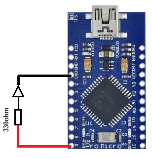
Connecting with Arduino First Time
- Open Arduino IDE:
Before you begin, make sure you have the Arduino IDE (Integrated Development Environment) installed on your computer. If you haven't already, you can download it from the Arduino software page: Arduino IDE Download
- Connect the Board to Your Computer:
Next, connect your Arduino Micro Pro or Leonardo board to your computer using a USB cable. Ensure that you use a data USB cable, as a charge-only cable will not work. The USB connection serves the dual purpose of powering the board and allowing the IDE to communicate with it.
- Select the Board:
Launch the Arduino IDE and click on "Tools" in the menu bar. In the "Board" row, you need to specify the board you are using for your sketch. If a board is already selected, it will be displayed here.
- Hover over the "Board" row to reveal the installed board packages.
- Click on the "Arduino Micro" or "Arduino Leonardo" board to select the appropriate one for your project.
For more details on board selection, you can visit the Arduino website's official documentation: Arduino Board Selection
- Select the Port:
In the Arduino IDE, click on "Tools" again, and this time find the "Port" row. It will display the serial devices available for communication.
- Select the serial device that corresponds to your Arduino board from the "Tools | Serial Port" menu. The port name will likely be something like "COM3" or higher (COM1 and COM2 are usually reserved for hardware serial ports).
- If you are unsure which port is the Arduino board, you can disconnect the board, reopen the menu, and note which entry disappears. Reconnect the board, and that entry should represent your Arduino board. Select that serial port.
5. Upload a sketch
- Write or Copy the Code: Begin by writing your Arduino sketch code in the Arduino IDE. If you have an existing code, you can copy it into the IDE.
- Verify the Code: Before uploading the code to the board, it's a good practice to click the "Verify" button (checkmark icon) to compile the sketch. This step helps to identify any syntax errors or issues in your code. If there are errors, the IDE will display them in the message window at the bottom. Fix the errors before proceeding to the next step.
- Upload the Code: Once your code has been verified successfully, it's time to upload it to the Arduino Micro Pro or Leonardo board. Click the "Upload" button (right-facing arrow icon) in the IDE. The IDE will compile the sketch again, and then it will start uploading it to the board. During the upload process, you may see the onboard LED on the Arduino board blinking rapidly.
- Running the Sketch: After successful uploading, your sketch will automatically start running on the board. It will continue running whenever the board is reset, powered on, or connected to a power source.
- Open the Serial Monitor: To interact with your sketch and view any output or debugging messages, you can open the Serial Monitor. Click on the icon in the upper right corner of the Arduino IDE. The Serial Monitor provides a communication interface between the Arduino board and your computer, allowing you to send and receive data.
Code:
This is a simple Arduino sketch that blinks an LED connected to pin 9 and provides status updates on the Serial Monitor:
// Define the LED pin
const int ledPin = 9;

void setup() {
  // Initialize the LED pin as an output
  pinMode(ledPin, OUTPUT);

  // Start the Serial communication at 9600 bps
  Serial.begin(9600);
}

void loop() {
  // Blink the LED on pin 9
  digitalWrite(ledPin, HIGH);    // Turn the LED on
  Serial.println("LED is ON");   // Print status on Serial Monitor
  delay(1000);                   // Wait for 1 second

  digitalWrite(ledPin, LOW);     // Turn the LED off
  Serial.println("LED is OFF");  // Print status on Serial Monitor
  delay(1000);                   // Wait for 1 second
}
-
We first define a constant integer variable
ledPinwith a value of 9, representing the pin number on the Arduino board to which the LED is connected. -
In the
setup()function, which is executed once when the Arduino board starts or resets, we perform the initial setup:- We configure the
ledPinas an output using thepinMode()function, which prepares the pin to send electrical signals to control external components. - We start the Serial communication with the computer at a baud rate of 9600 bits per second using
Serial.begin(9600), allowing us to communicate with the Arduino via the Serial Monitor.
- We configure the
-
In the
loop()function, which runs repeatedly after thesetup()function, we create a blinking effect for the LED:- We turn the LED on by setting
ledPinto a HIGH state usingdigitalWrite(ledPin, HIGH). - We print the status message "LED is ON" to the Serial Monitor using
Serial.println("LED is ON"). - We introduce a 1000 milliseconds (1-second) delay using
delay(1000), keeping the LED on for 1 second. - We turn the LED off by setting
ledPinto a LOW state usingdigitalWrite(ledPin, LOW). - We print the status message "LED is OFF" to the Serial Monitor using
Serial.println("LED is OFF"). - We introduce another 1000 milliseconds (1-second) delay using
delay(1000), keeping the LED off for 1 second.
- We turn the LED on by setting
Technical Details:
-
Microcontroller:- ATmega32U4
-
Operating Voltage:- 5
-
Input Voltage:- 5 - 12 V ( If use 5V, input 5V to Vcc, if used above 5V, input to RAW pin)
-
Mini USB Connector
-
9 x 10-bit Analog input pins
-
18 x digital I/O pins
-
5 x PWM pins
-
RX/TX serial port
- Flash Memory: 32KB
- SRAM: 2.5KB
-
Clock Speed 16MHz
-
5v regulating circuit
- Pin 13 LED no
- Dimension: 3.98cm x 2.29cm
Resources:
- You might also want to look at: the reference for the Arduino language.
- Getting Started Tutorial
- The Sparkfun Version Tutorial
- Arduino Board Selection
- Arduino IDE Download
Comparisons:
In comparing the Arduino Pro Micro with Mini USB Port (Compatible) and Arduino Leonardo (Compatible) the main differences between the Arduino Pro Micro with Mini USB Port (Compatible) and the Arduino Leonardo (Compatible) lie in their size, USB port type, and the number of PWM pins. Both boards share similar microcontrollers and functionalities, making them versatile options for a wide range of electronics projects. The choice between them would largely depend on the specific requirements and size constraints of the project at hand:
-
Size and Form Factor:
- Arduino Pro Micro: The Pro Micro is compact and designed for space-constrained projects, measuring around 34mm x 18mm.
- Arduino Leonardo: The Leonardo is slightly larger than the Pro Micro, with dimensions of approximately 68mm x 53mm.
-
Microcontroller:
- Arduino Pro Micro: The Pro Micro is powered by the ATmega32U4 microcontroller, which offers 32KB of flash memory and 2.5KB of SRAM. It also features built-in USB communication capabilities.
- Arduino Leonardo: Like the Pro Micro, the Leonardo is equipped with the ATmega32U4 microcontroller, providing similar memory and USB functionalities.
-
USB Port:
- Arduino Pro Micro: The Pro Micro has a Mini USB port, which is smaller than the standard USB Type-A port but larger than the Micro USB port.
- Arduino Leonardo: The Leonardo features a standard USB Type-B port for communication and power.
-
Input/Output Pins:
- Arduino Pro Micro: The Pro Micro has 18 digital I/O pins and 9 analog input pins, allowing for various sensor connections and interfacing with external devices.
- Arduino Leonardo: The Leonardo also provides 20 digital I/O pins and 12 analog input pins, offering similar capabilities as the Pro Micro.
-
PWM Pins:
- Arduino Pro Micro: The Pro Micro offers 5 PWM pins, enabling precise control of devices like motors and LEDs.
- Arduino Leonardo: The Leonardo provides 7 PWM pins, giving slightly more PWM options compared to the Pro Micro.
-
Operating Voltage:
- Arduino Pro Micro: The Pro Micro operates at 5V, making it compatible with 5V sensors and components.
- Arduino Leonardo: The Leonardo can be powered at either 5V or 3.3V, providing more flexibility in certain applications.
-
Compatibility:
- Both boards are Arduino-compatible, meaning they can be programmed and used with the Arduino IDE and follow the same principles of work.