AED 40.95
Description
The module is a wireless transceiver that uses Silicon Labs' Si4432 chip with a maximum output power of +20dBm, making it suitable for RF signal amplification development. It operates in the frequency range of 433.92 MHz with a data transfer rate of 0.123-256 kbps and supports FSK, GFSK, and baton modulation modes. The module has a low consumption shutdown mode, digital RSSI, and timing wake-up function. It also has a 4-wire serial data flow bus and can be used for remote control, remote meter reading, industrial control, sensor networks, and more.
Package Includes:
- 1 x Wireless SI4432 Up to 1000m Module
- 1 x Pin headers
- 1 x External antenna
Features:
- The module uses Silicon Labs' Si4432 as its wireless transceiver chip, which provides stable performance and low power consumption.
- The frequency range of the module is 433.92 MHz.
- The module has a maximum output power of up to +20 dBm, which allows for the development of RF signal amplification.
- The module supports data transfer rates ranging from 0.123 to 256 kbps.
- The module supports FSK, GFSK, and OOK modulation modes.
- The module can operate on a power supply of 1.8-3.6V.
- The module has a low-power shutdown mode.
- The module has a digital RSSI (Received Signal Strength Indicator) that provides information on the strength of received signals.
- The module has a timing wake-up function.
- The module supports automatic antenna matching and two-way switch control.
Description:
The module described is a wireless transceiver module based on Silicon Labs' Si4432 IC, which is a small, full-featured, and low-power wireless transceiver chip. It operates on a frequency range of 433.92 MHz and has a maximum output power of up to +20 dBm, making it suitable for RF signal amplification development. The module is designed to be easy to use and provides stable and reliable wireless communication solutions without requiring in-depth radio knowledge. The module supports various modulation modes such as FSK, GFSK, and OOK, and has a sensitivity of up to 121 dBm. It can transfer data at a rate of 0.123-256 kbps, making it suitable for a wide range of applications. The module operates on a power supply of 1.8-3.6V and has a low consumption shutdown mode, which helps to conserve power. The pinout of the module includes 14 pins, which are used for power supply, digital input, and output, serial data input and output, serial clock input, interrupt output, and antenna connection. The module also features a received signal strength indicator (RSSI) and timing wake-up function.
Principle of Work:
The Si4432 is a highly configurable transceiver that operates on a frequency range of 240-960 MHz and supports FSK, GFSK, and OOK modulation. It supports up to 20dBm output power, which makes it possible to transmit signals over long distances. To interface with the module, you will need to connect it to a microcontroller via a four-wire serial interface, which includes serial data input (SDI), serial data output (SDO), serial clock (SCLK), and chip select (nSEL) pins. The module also provides an interrupt output (nIRQ) pin to indicate when data is available for transmission or reception. The Si4432 module can be controlled by sending and receiving commands and data through the serial interface. For example, to transmit data, the microcontroller sends a command to the module to set the frequency, modulation type, and output power. Then, it sends the data to be transmitted through the serial interface. When the transmission is complete, the module sends an interrupt to the microcontroller indicating the status of the transmission. To receive data, the module continuously monitors the airwaves for incoming signals. When a signal is detected, the module decodes it and sends the received data to the microcontroller through the serial interface. The microcontroller can then process the data or send a response back through the Si4432 module.
Pinout of the Module:
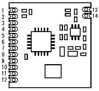
| Number | Pins | Description |
|---|---|---|
| 1 | GND | N/A |
| 2 | GPIO0 | Internal has connected the receiving control module feet |
| 3 | GPIO1 | Internal has connected the receiving control module feet |
| 4 | GPIO2 | Connect the chip GPIO2 pins directly |
| 5 | VCC | Connect power positive 3.3 V |
| 6 | SDO | 0 ~ VDDV digital output, provide the internal control of the register serial back to read function |
| 7 | SDI | Serial data input. 0 ~ VDD V digital input. The pins for the 4-wire serial data flow bus. |
| 8 | SCLK | A serial clock input. 0 ~ VDDV digital input. The pins provide the 4-wire serial data clock function |
| 9 | nSEL | Serial interface choice input pins. 0 ~ VDDV digital input. The pins for the 4 wire serial data bus provides the choice/make can function, this signal is used to indicate a read/write mode |
| 10 | nIRQ | Interrupt output pins |
| 11 | SDN | Close input pins. 0 ~ VDDV digital input. In addition to shutting down all the mode SDN = 0. When SDN = 1 chip will be completely shut down and the content of the register will be lost. |
| 12 | GND | N/A |
| 13 | ANT | Pick up the coaxial antenna 50 |
|
14
|
GND | N/A |
Applications:
- Remote Control: The module can be used to develop remote control devices such as garage door openers, remote switches, and remote keyless entry systems.
- Remote Meter Reading: It can be used in automatic meter reading systems for electricity, water, and gas meters.
- Home Security Alarm and Remote Keyless Entry: The module can be used to develop security systems for homes, offices, and other buildings. It can also be used to develop remote keyless entry systems for cars and other vehicles.
- Industrial Control: The module can be used to develop industrial control systems such as process automation, monitoring and control systems, and machine-to-machine communication.
- Home Automation Telemetry: It can be used in home automation systems to control and monitor various devices such as lights, temperature, and security systems.
- Personal Data Record: The module can be used to develop personal data recorders such as heart rate monitors, pedometers, and blood glucose monitors.
- Toy Control: The module can be used to develop remote-controlled toys such as cars, planes, and boats.
- Sensor Networks: The module can be used to develop wireless sensor networks for environmental monitoring, agriculture, and other applications.
- Tire Pressure Monitoring: The module can be used to develop tire pressure monitoring systems for vehicles.
- Health Monitoring: It can be used in health monitoring systems for patients in hospitals and home health care settings.
- Wireless PC Peripherals: The module can be used to develop wireless PC peripherals such as wireless keyboards, mice, and printers.
- Tag Reader: It can be used in RFID tag readers for inventory tracking and asset management.
Circuit:
For both receiving and transmitting connections like on the next table you will need two Boards and two modules.
| Si4432 | Arduino |
|---|---|
| GND | GND |
| VCC | 3.3V |
| SDN | 3.3V (or a digital pin, if you want to be able to turn the module on and off) |
| nIRQ | A digital pin (this pin will be used as an interrupt pin for the receiver) |
| SCK | D13 |
| MISO | D12 |
| MOSI | D11 |
| NSS | D10 |
Note that the Si4432 module operates at 3.3V, so you should not connect it directly to the 5V pins on the Arduino. You can use a voltage level shifter or a voltage divider to convert the signals if needed.
Library:
The RadioHead library on the Arduino IDE installation steps:
- Open the Arduino IDE.
- Select
Sketch>Include Library>Manage Libraries...from the menu. - In the Library Manager, search for "RadioHead" in the search bar.
- Click on the
RadioHeadlibrary in the search results to select it. - Click the
Installbutton to install the library. - Wait for the installation to complete. Once it's finished, you should see a message in the status bar indicating that the installation was successful.
Code:
Example code for using the Si4432 module with Arduino as a transmitter and receiver.
Transmitter Code:
#include "RH_ASK.h"     // Include RadioHead library
RH_ASK driver;          // Create an instance of the driver

void setup() {
  Serial.begin(9600);   // Initialize serial communication
  while (!Serial);      // Wait for serial monitor to open
  if (!driver.init()) { // Initialize the driver
    Serial.println("RadioHead driver init failed");
  }
}

void loop() {
  const char *msg = "Hello, world!";    // Define the message to be sent
  driver.send((uint8_t *)msg, strlen(msg)); // Send the message
  driver.waitPacketSent();              // Wait for the message to be sent
  Serial.println("Message sent");
  delay(1000);                          // Wait for 1 second before sending the next message
}
The transmitter code initializes the RH_ASK driver, which is an instance of the RadioHead library's ASK driver. The code then enters the loop() function, where it sends a message "Hello, world!" using the driver.send() function. The message is converted to an array of bytes using uint8_t, and its length is obtained using strlen(). After sending the message, the code waits for the message to be sent using driver.waitPacketSent() and prints a message to the serial monitor indicating that the message has been sent. The code then waits for 1 second using delay(1000) before sending the next message.
Receiver Code:
#include "RH_ASK.h"     // Include RadioHead library
RH_ASK driver;          // Create an instance of the driver

void setup() {
  Serial.begin(9600);   // Initialize serial communication
  while (!Serial);      // Wait for serial monitor to open
  if (!driver.init()) { // Initialize the driver
    Serial.println("RadioHead driver init failed");
  }
}

void loop() {
  uint8_t buf[50];       // Create a buffer to hold the received message
  uint8_t buflen = sizeof(buf);
  if (driver.recv(buf, &buflen)) {  // Receive the message
    Serial.print("Message received: ");
    Serial.println((char *)buf);    // Print the message to the serial monitor
  }
}
The receiver code also initializes the RH_ASK driver and waits for a message to be received using driver.recv(). If a message is received, it is stored in a buffer buf and its length is stored in buflen. The code then prints the message to the serial monitor using Serial.println(). The loop() function then loops back and waits for the next message to be received.
Technical Details:
- penetrating ability SI4432 IC, stable performance
- Frequency Range: 433.92 M
- Sensitivity up to 121 DBM
- The Maximum output power: 20 DBM
- The Data transfer rate: 0.123-256 KBPS
- FSK, GFSK, and baton modulation mode
- 1.8-3.6 V power supply
- Low consumption shutdown mode
- Digital, a received signal strength indicator (RSSI)
- Timing wake-up function
- The can antenna automatically be used to match The and two - way the switch control
Resources:
Comparison:
The Si4432 and nRF24 are both popular RF (radio frequency) modules that can be used with microcontrollers like Arduino for wireless communication. However, they have some key differences that may make one more suitable for a particular application than the other. Here are some of the differences between the two modules:
- Frequency Range: The Si4432 operates at a wider frequency range of 240-930 MHz, while the nRF24 operates at a narrower range of 2.4 GHz. This means that the Si4432 may be more suitable for long-range communication applications, whereas the nRF24 is better suited for applications that require higher data rates over shorter distances.
- Data Rate: The nRF24 has a higher maximum data rate of 2 Mbps, while the Si4432 has a maximum data rate of 256 kbps. This makes the nRF24 more suitable for applications that require high data rates, such as audio and video transmission.
- Power Consumption: The nRF24 has a lower power consumption compared to the Si4432. This makes it more suitable for battery-powered applications, where power consumption is a critical factor.
- Price: The nRF24 is generally less expensive than the Si4432, making it a more budget-friendly option for hobbyists and small-scale projects.
- Ease of Use: The nRF24 has a simpler interface and is easier to use than the Si4432, which requires more complex configuration and tuning.
The choice between the Si4432 and nRF24 depends on the specific requirements of your project. If you need long-range communication with lower data rates and more complex configuration requirements, the Si4432 may be a better choice. If you need higher data rates, lower power consumption, and a simpler interface, the nRF24 may be a better option.