AED 8.40
Description
The Hall effect Module is based on the 3144 IC and outputs digital data. This hall effect sensor is smaller in size, uses less power, and is simple to connect to any type of controller. A magnetic sensor detecting circuit, voltage adjustment device, Hall voltage generator, differential amplifier, Schmitt trigger, temperature compensation circuit, and an open collector output stage are all part of the module. The intensity of magnetic induction is supplied, and the output is a digital voltage signal.
Package Includes:
- 1x Hall Effect Sensors Module A3144E 4pin
Features:
- This Module includes digital Schmitt trigger output and digital output in real time on A0
- The comparator output indicator light control distance is measured: less than 1CM
- Indicator LEDs
- Stable and Accurate Output
- Mounting screw hole
- 4.5 V to 24 V Operation … Needs Only An Unregulated Supply
- Open-Collector 25 mA Output … Compatible with Digital Logic
- Activate with Small, Commercially Available Permanent Magnets
- Solid-State Reliability
- Resistant to Physical Stress
- Compatible with Arduino
Description:
The hall effect, in short, is a relationship between electric and magnetic fields through a semiconductor that allows electricity to flow when a magnetic field is applied within the vicinity of a given hall sensor. In our case, we will be using the A3144 hall effect sensor, which is a unipolar sensor. Unipolar sensors are great for scenarios where only one pole of a magnet is needed. This allows us to stick a magnet to a moving object and as it cycles through its rotation, each time it passes the hall sensor, the hall sensor registers its passing and we can say that one period has been completed.
Principle of Work:
In a nutshell, the hall effect is a relationship between electric and magnetic fields that allows electricity to flow when a magnetic field is applied near a given hall sensor. In our case, we'll be using a unipolar hall effect sensor called the A3144. Unipolar sensors are ideal for situations where only one magnet pole is required. This enables us to attach a magnet to a moving object, and as it rotates, each time it passes the hall sensor, the hall sensor registers its passing, and we can say that one period has been completed.
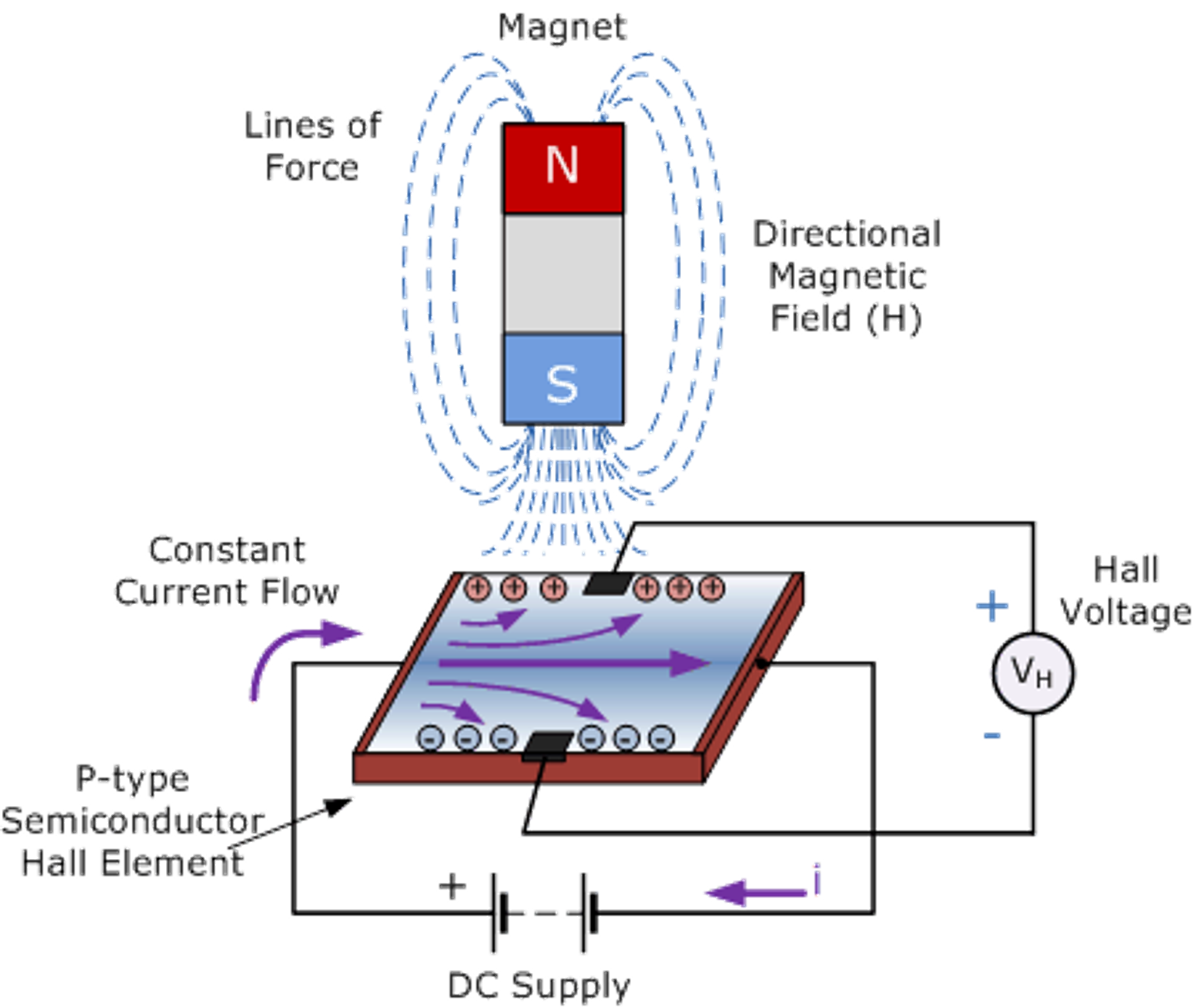
The Hall Sensor detects the Hall Effect, which is caused by a voltage difference across an electrical conductor that is transverse to an electric current in the conductor, as well as a magnetic field perpendicular to the current. When a magnetic field perpendicular to the Hall sensor exceeds the BOP threshold, the output of the Hall sensor switches low and turns on, and it switches high and turns on when the magnetic field disappears. And the comparator circuit, which improves the reliability of the output signal.
Pinout of the Board:
The Hall output voltage in real-time of the module can be determined by (AO), while the digital output (DO) merely functions as a switch that turns on/off when a magnet is nearby
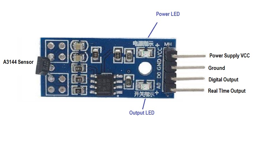
- VCC: positive power supply 3.3-5V
- GND: a negative one
- DO: digital output module, the output of low magnetic induction
- AO: Hall output voltage in real-time
Applications:
- Brushless DC electric motors to detect the position of the permanent magnet.
- Computer printers to detect missing paper and open covers.
- General switch applications
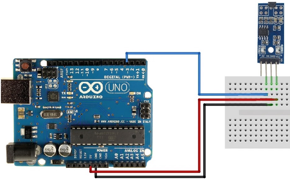
Circuit:
The digital pin D0 of the module is connected to the pin3 on Arduino, the 5v and GND should be connected as you see in the schematic that follows.
Library:
No Need for Library for this module
Code:
We will turn on the LED on pin 13 when you put a magnet near the module.
int led = 13;//LED pin
int sensor = 3; //sensor pin
int val; //numeric variable
void setup()
{
	pinMode(led, OUTPUT); //set LED pin as output
	pinMode(sensor, INPUT); //set sensor pin as input
}
void loop()
{
	val = digitalRead(sensor); //Read the sensor
	if(val == LOW) //when magnetic field is detected, turn led on
	{
		digitalWrite(Led, HIGH);
	}
	else
	{
		digitalWrite(Led, LOW);
	}
}
Technical Details:
- Size: 32mm X 14mm
- Mounting screw hole: 3mm
- Power: DC 3-5.5v
- Output capability: 16mA
- Power indicator: Yes
- The comparator output indicator light control distance is measured: less than 1CM
Resources:
Comparisons:
The 3144E 4 Pins Module is based on the 3144EUA-S hall-effect sensor and operates at a higher voltage range of 4.5V to 24V. As a result, the 3144E 4 Pins Module can be connected to an Arduino but not to an ESP8266 or ESP32 microcontroller board due to the low operating voltage of 3.3V. The KY-024 module is based on the SS49E hall-effect sensor, which operates between 2.7V and 6.5V. This voltage range is ideal for our Arduino microcontrollers, which operate at 5V, as well as the ESP8266 and ESP32 microcontrollers, which operate at 3.3V. The KY-024 module is larger than the 3144E 4 Pins Module because it measures the analog signal as well as generates a digital signal. The repositioning of the hall-effect sensor is the most significant difference between the KY-024 and3144E 4 Pins Module. When there is no magnetic field or when the magnetic field is weaker, the KY-024 returns to its initial state. The 3144EUA-S hall-effect sensor in the3144E 4 Pins Module, on the other hand, retains its state even when there is no longer a magnetic field. The 3144E 4 Pins Module is repositioned using the magnetic field's opposite polarity.
| Function | KY-024 | 3144E 4 Pins Module |
|---|---|---|
| Hall-Effect Sensor | SS49E | 3144E |
| Operating voltage | 2.7V...6.5V | 4.5V...24V |
| Board dimensions | 1.5 cm x 3.6 cm0.6 in x 1.4 in | 32mm X 14mm |
| Outputs | Analog + Digital | Digital |
| Build in resistor | 100kΩ potentiometer | - |
| Reposition | No/weak magnetic field | Opposite polarity of magnetic field |