AED 19.75
Description
The PCF8591 is an analog-to-digital converter (ADC) module with 4 analog input channels that can be utilized as 2 differential inputs. It operates on the I2C protocol and uses a successive approximation conversion process. a digital-to-analog converter (DAC) is included, allowing for analog output. the number of ADC inputs can be increased to 32 and DAC outputs to 8 by adding more modules.
Package Includes:
- 1 x PCF8591 Analog-To-Digital Converter Module
Features:
- The PCF8591 is a mixed-signal integrated circuit that includes an ADC and a DAC.
- It features 4 analog inputs, which can also be used as two differential inputs.
- The device operates using I2C communication protocol and uses a successive approximation conversion process, similar to that of the ADC in an Arduino.
- The PCF8591 also includes a DAC, which provides an analog output.
- It has an 8-bit resolution for the ADC and a separate ground input, which helps reduce noise.
- The device supports up to 7 additional chips on the same I2C bus, providing a total of 32 analog ADC inputs and 8 DAC analog outputs.
- The PCF8591 is useful for applications that require both ADC and DAC functionality and multiple analog inputs.
- Its compact size, I2C communication, and low power consumption make it a popular choice for many projects and applications.
Description:
The PCF8591 is a versatile analog-to-digital converter (ADC) that can perform conversions on four analog inputs, which can be configured as two differential inputs. It utilizes a successive approximation conversion process, which is similar to the ADC operation in Arduino. The device is I2C-compatible and can be connected to other I2C devices to expand the number of analog inputs to 32 and the number of analog outputs to 8 through the integration of up to seven additional chips. Despite having only an 8-bit resolution, the PCF8591 also has a digital-to-analog converter (DAC) that allows for analog output. To reduce noise, the PCF8591 has a separate GND input that separates the grounds.
Principle of Work:
The PCF8591 is an 8-bit analog-to-digital converter (ADC) with 4 analog inputs. It operates using the I2C protocol and uses a successive approximation conversion process to convert analog signals into digital values. The device has a separate ground input which helps in reducing noise and improving the overall accuracy of the ADC. The ADC supports both single-ended and differential input modes, allowing the use of two differential inputs. The PCF8591 also has a digital-to-analog converter (DAC) which provides an analog output. Up to seven additional chips can be added to the same I2C bus, providing a total of 32 analog ADC inputs and 8 DAC analog outputs. The ADC has an 8-bit resolution which provides a range of 256 steps between the minimum and maximum input voltage. The DAC, on the other hand, has a resolution of 8 bits and can produce a range of voltages between 0V and Vref. The ADC and DAC are both controlled through the I2C bus, allowing for easy integration with other microcontrollers and systems.
Pinout of the Module:
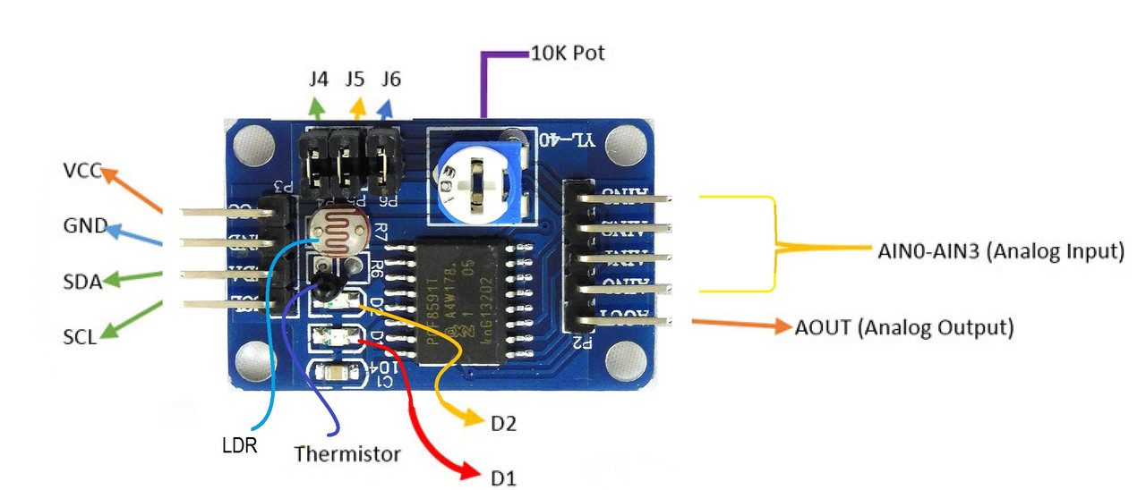
- VCC: This is the power pin and is used to supply power to the module.
- GND: This is the ground pin and is used to provide a reference voltage for the ADC and DAC.
- SDA: This is the serial data pin and is used to transfer data between the ADC and the microcontroller (such as an Arduino) using the I2C protocol.
- SCL: This is the serial clock pin and is used to synchronize the data transfer between the ADC and the microcontroller using the I2C protocol.
- A0-A3: These are analog input pins and are used to read analog signals from external devices such as thermistors or LDRs.
-
The module also includes a thermistor and an LDR (Light Dependent Resistor) for measuring temperature and light levels, respectively. The module also includes jumpers for configuring the address of the I2C bus, as well as an alert pin for triggering an interrupt when a conversion is completed.
Applications:
- Sensing and measurement systems: The module can be used for measuring various physical parameters like temperature, humidity, pressure, light intensity, etc.
- Industrial control systems: The module can be used for monitoring and controlling various industrial processes, like temperature, pressure, or flow control.
- Automation systems: The module can be used in automation systems for monitoring and controlling various parameters like temperature, humidity, light intensity, etc.
- Robotics: The module can be used in robotics projects for controlling various sensors and actuators.
- Testing and Debugging: The module can be used in testing and debugging systems for measuring various physical parameters.
- Educational purposes: The module can be used in educational projects for students to learn about ADC and its working principles.
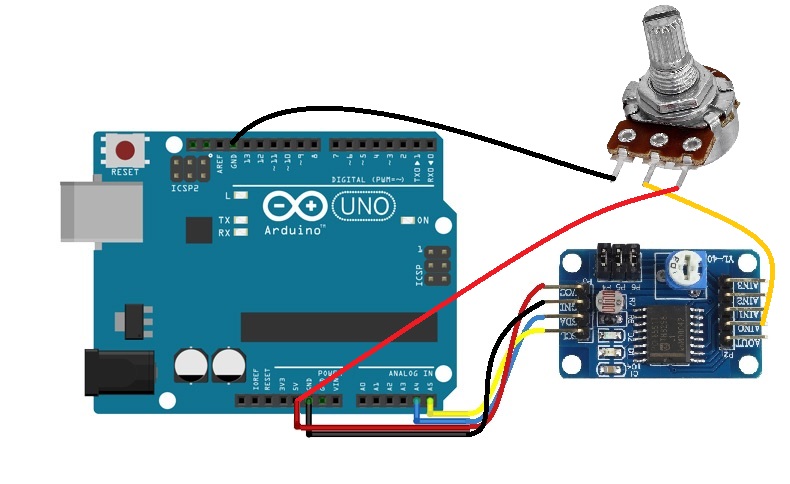
Circuit:
- Connect the PCF8591 to the A4 (SDA) and A5 (SCL) pins of the Arduino board.
- Connect the VCC and GND pins of the PCF8591 to the corresponding power pins on the Arduino.
- Connect the VCC and GND pins of the pot to the corresponding power pins on the Arduino.
- the middle of the pot connected to A0 on the module
Library:
No need to install any Library.
Code:
example code in C++ for using the PCF8591 with a potentiometer connected to input channel A0, and the module connected to the I2C bus on A5 (SDA) and A4 (SCL) pins of an Arduino Uno:
#include "Wire.h"

const int PCF8591 = 0x48; // I2C address of the PCF8591

void setup() {
  Serial.begin(9600);
  Wire.begin();
}

void loop() {
  int value;

  Wire.beginTransmission(PCF8591);
  Wire.write(0x40); // Select channel 0
  Wire.endTransmission();

  Wire.requestFrom(PCF8591, 1); // Request 1 byte
  if (Wire.available()) {
    value = Wire.read();
  }

  Serial.println(value);
  delay(100);
}
This code sets up a serial communication at 9600 baud and initializes the I2C bus. In the loop function, it selects channel 0 (A0) on the PCF8591 and reads 1 byte of data (the 8-bit ADC value). The value is then printed to the serial monitor and the loop is repeated every 100 milliseconds.
Technical Details:
- Resolution: 8-bit (0 to 255)
- Sampling rate: up to 8 samples per second
- Input voltage range: 0-VCC (typically 5V)
- Input channels: 4 single-ended or 2 differential inputs
- Interface: I2C
- Supply voltage: 2.5V to 6V
- Operating temperature: -40°C to +85°C
- Package type: DIP
Resources:
Comparisons:
The ADS1115 and PCF8591 are both Analog-to-Digital converters (ADCs) used for converting analog signals to digital signals. However, there are some differences between the two:
- Resolution: The ADS1115 has a higher resolution of 16 bits compared to the PCF8591's 8-bit resolution.
- Sampling rate: The ADS1115 has a faster sampling rate of up to 860 samples per second, compared to the PCF8591's 8 samples per second.
- Input channels: The ADS1115 has four input channels, while the PCF8591 has only one.
- Power requirements: The PCF8591 is powered by a single +5V supply, while the ADS1115 requires a separate +3V supply.