AED 19.95
Description
The TLP281 is a 4-channel optoisolator module that provides electrical isolation between input and output signals. It uses a light-emitting diode (LED) to transmit signals across an isolation barrier to a phototransistor. This allows for high-voltage and/or high-frequency signals to be transmitted without interference or damage to the receiving circuitry. The TLP281 is commonly used in industrial automation, motor control, and digital signal isolation applications. It features a compact size, low power consumption, and high isolation voltage, making it a reliable and versatile choice for many applications.
Package Includes:
- 1 x TLP281 4-Channel Optoisolator Module
Features:
- Four Channels: The module has four independent channels, which allows it to provide electrical isolation for up to four input/output signal pairs.
- High Isolation Voltage: The TLP281 module is designed to provide high levels of isolation, with a maximum isolation voltage of 5,000 volts RMS.
- Low Power Consumption: The module has a low power consumption, making it an energy-efficient choice for many applications.
- Compact Size: The TLP281 is designed to be compact and space-saving, making it easy to integrate into existing systems.
- High Speed: The module is capable of high-speed signal transmission, making it suitable for applications that require fast response times.
- Low Coupling Capacitance: The TLP281 has a low coupling capacitance, which helps to minimize signal distortion and ensure accurate signal transmission.
- RoHS Compliant: The module is RoHS compliant, which means it meets the European Union's Restriction of Hazardous Substances directive.
- Wide Temperature Range: The TLP281 can operate over a wide temperature range, making it suitable for use in harsh environments.
- High Reliability: The module is designed to be highly reliable, with a long operating life and low failure rate.
- Easy to Use: The TLP281 is designed to be easy to use, with a simple interface that makes it easy to integrate into existing systems.
Description:
The TLP281 is a 4-channel optoisolator module that is commonly used in applications where there is a need to provide electrical isolation between input and output signals. It can be used to protect sensitive circuitry from high-voltage or high-frequency signals that could cause damage or interfere with the performance of the system. The module is built around a light-emitting diode (LED) and a phototransistor. When an electrical signal is applied to the LED, it emits light that is transmitted across an isolation barrier to the phototransistor. The phototransistor then responds to the light and produces an electrical signal that is an exact replica of the input signal. Because the signal is transmitted optically, there is no direct electrical connection between the input and output circuits, providing complete electrical isolation. The TLP281 module is designed to be compact and easy to use, with a low power consumption and a high isolation voltage. It can be used in a wide range of applications, including industrial automation, motor control, digital signal isolation, and more. It is particularly useful in applications where there is a need to protect sensitive circuitry from high-voltage or high-frequency signals. One of the key features of the TLP281 is its high isolation voltage. It can provide isolation up to 5,000 volts RMS, making it ideal for use in applications where there is a need to provide high levels of protection. It is also designed to be easy to use, with a simple interface that allows for easy integration into existing systems.
Principle of Work:
- The TLP281 4-channel optoisolator module works on the principle of optical isolation. It uses an LED and a photo-transistor in each channel to isolate the input signal from the output signal. When a voltage is applied to the input side of the module, the LED is turned on, which in turn activates the photo-transistor on the output side of the module.
- The input side of the module consists of four digital input pins (IN1-IN4) and a ground pin (GND). When a voltage is applied to any of the input pins, the LED corresponding to that input is turned on, and light is emitted toward the photo-transistor on the output side.
- The output side of the module consists of four output pins (OUT1-OUT4), an output ground pin (HGND), and an output base voltage pin (HVCC). The photo-transistor receives the light from the LED and allows current to flow through it, which in turn allows the voltage to appear on the output pins. The output base voltage pin (HVCC) provides the power supply for the output side of the module.
Pinout of the Module:
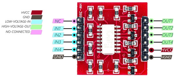
- HVCC: Output Base Voltage – (Max 24V): This pin is the output base voltage for the optoisolator. It is used to power the output side of the module and has a maximum voltage rating of 24V.
- HGND: Output Ground: This pin is the ground for the output side of the module.
- GND: Input Ground: This pin is the ground for the input side of the module.
- IN1: Digital Input 1: This pin is the input for channel 1. It is used to input digital signals to the optoisolator.
- IN2: Digital Input 2: This pin is the input for channel 2. It is used to input digital signals to the optoisolator.
- IN3: Digital Input 3: This pin is the input for channel 3. It is used to input digital signals to the optoisolator.
- IN4: Digital Input 4: This pin is the input for channel 4. It is used to input digital signals to the optoisolator.
- OUT1: Output 1: This pin is the output for channel 1. It provides the optically isolated digital signal output.
- OUT2: Output 2: This pin is the output for channel 2. It provides the optically isolated digital signal output.
- OUT3: Output 3: This pin is the output for channel 3. It provides the optically isolated digital signal output.
- OUT4: Output 4: This pin is the output for channel 4. It provides the optically isolated digital signal output.
- NC: Not Used Pin: This pin is not used and is left unconnected
Applications:
- Industrial Control Systems: The module can be used in industrial control systems to isolate the control signals from the power circuits, thereby improving safety and reliability.
- Motor Control: The module can be used in motor control circuits to isolate the control signals from the high-power motor circuits, helping to prevent electrical noise and voltage spikes from interfering with the control signals.
- Power Supply Isolation: The module can be used in power supply circuits to provide electrical isolation between different parts of the circuit, helping to improve safety and reliability.
- Medical Equipment: The module can be used in medical equipment to provide electrical isolation between different parts of the circuit, helping to improve patient safety and prevent electrical interference.
- Audio Equipment: The module can be used in audio equipment to isolate the audio signals from other electrical circuits, helping to prevent noise and interference from affecting the audio quality.
- Digital Circuit Isolation: The module can be used in digital circuits to isolate different parts of the circuit, helping to prevent electrical noise and voltage spikes from affecting the signals.
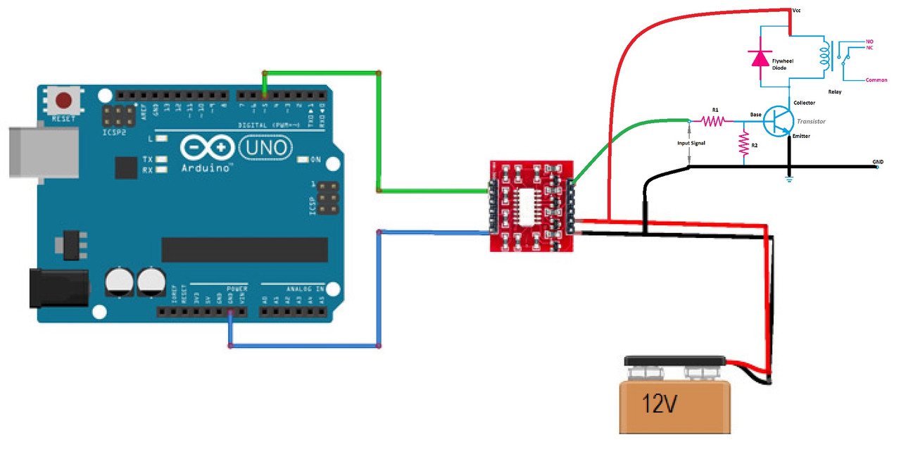
Circuit:
The circuit below shows how to link an Arduino to a TLP281 module and use it to drive a relay circuit with full voltage isolation. Attach the cables as needed:
Library:
No library installation needed
Code:
This is an Arduino code that can drive a relay through a TLP281 module using the input pin 5, which can be turned on or off using the serial monitor:
int inputPin = 5;
int relayPin = 10;
int state = 0;

void setup() {
  pinMode(inputPin, INPUT);
  pinMode(relayPin, OUTPUT);
  Serial.begin(9600);
}

void loop() {
  if (Serial.available() > 0) {
    state = Serial.read() - '0'; // read the input value from the serial monitor and convert it to an integer
  }

  digitalWrite(relayPin, LOW); // turn off the relay

  if (digitalRead(inputPin) == HIGH && state == 1) { // if the input pin is high and the state is 1
    digitalWrite(relayPin, HIGH); // turn on the relay
  }

  delay(100); // delay to avoid serial communication errors
}
To use this code, upload it to your Arduino board and open the serial monitor. Type "1" to turn on the relay and "0" to turn it off. Make sure you have connected the TLP281 module input pin 5 to the Arduino input pin defined in the code, and the module output pins to the relay. Also, make sure you have connected the power supply and ground pins of the module to your circuit as in the scheme.
Technical Details:
- Isolation Voltage: 5,000 volts RMS (minimum)
- Input Voltage: 5V DC (maximum)
- Output Voltage: 55V DC (maximum)
- Output Current: 50mA (maximum)
- Operating Temperature Range: -40°C to +110°C
- Storage Temperature Range: -55°C to +125°C
- Rise and Fall Times: 18ns (maximum)
- Propagation Delay Time: 100ns (maximum)
- Power Consumption: 0.2mW (typical)
- Insulation Resistance: 10^12 ohms (minimum)
- Common Mode Transient Immunity (CMTI): 10kV/μs (minimum)
- PCB Size: 25*24mm/0.98*0.94
Resources:
Comparisons:
The TLP281 and MOC3041 are both optoisolator devices, but they have some differences in terms of their specifications and applications. Here are some of the key differences:
- Number of Channels: The TLP281 is a 4-channel optoisolator module, while the MOC3041 is a single-channel optoisolator IC.
- Isolation Voltage: The TLP281 has a higher isolation voltage of 5000 Vrms compared to the MOC3041's isolation voltage of 2500 Vrms.
- Output Type: The TLP281 has a phototransistor output, while the MOC3041 has a triac output. The phototransistor output can sink current, while the triac output can both sink and source current.
- Maximum Trigger Current: The MOC3041 has a higher maximum trigger current of 50 mA compared to the TLP281's maximum trigger current of 16 mA.
- Applications: The TLP281 is often used in digital circuits, motor control, and power supply isolation applications, while the MOC3041 is commonly used in AC power control applications such as lighting dimmers and motor speed controllers.
In the end, both the TLP281 and MOC3041 are optoisolator devices that provide electrical isolation between different parts of a circuit. The TLP281 is a 4-channel module with a higher isolation voltage and a phototransistor output, while the MOC3041 is a single-channel IC with a triac output and is commonly used in AC power control applications.