AED 12.50
Description
The DC-DC Buck Converter Step Down Module LM2596 is a small electronic module that can convert a higher DC voltage to a lower DC voltage. It can handle input voltages ranging from 4.5V to 35V and output voltages between 1.3V to 30V, with a maximum output current of 3A. The module has a compact size and is suitable for a variety of electronic projects, including power supplies, battery chargers, and LED lighting systems. It operates over a wide temperature range from -40 ℃ to +85 ℃, has load regulation of ±0.5%, and voltage regulation of ±2.5%.
Package Includes:
- 1 x DC-DC Buck Converter Step Down Module LM2596
Features:
- Compact and easy to integrate into electronic circuits
- Efficiently regulates the output voltage using the LM2596 integrated circuit
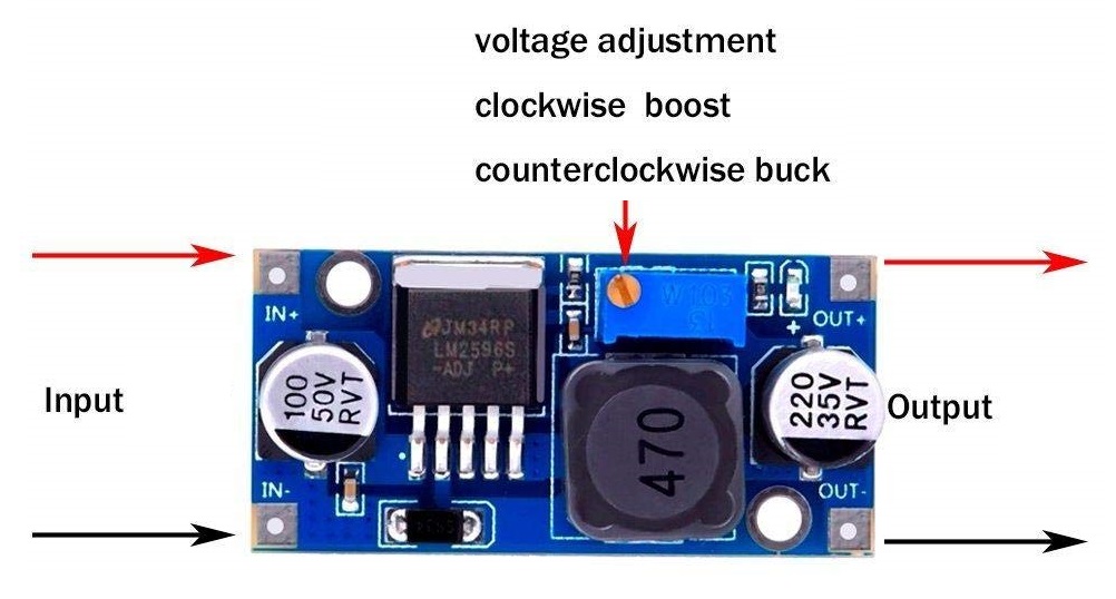
- Allows for adjusting the output voltage using a small potentiometer on the module
- Provides stable and reliable output voltage
- Suitable for use in a wide range of electronic projects, including power supplies, battery chargers, and LED lighting systems
- Non-isolated constant voltage module
- Non-synchronous rectification
- Input voltage range: 4.5V to 35V
Description:
The DC-DC Buck Converter Step Down Module LM2596 is a non-isolated constant voltage module with non-synchronous rectification. It can handle input voltages ranging from 4.5V to 35V and output voltages between 1.3V to 30V, with a maximum output current of 3A. The module has a switching frequency of 150KHz and an output ripple of up to 50mV (maximum) over a 20M bandwidth. It has load regulation of ±0.5% and voltage regulation of ±2.5%. The module operates over a wide temperature range from -40 ℃ to +85 ℃ and has a compact size of 48 * 23 * 14 mm (1 7/8 x 29/32 x 9/16 in), making it suitable for a variety of electronic projects, including power supplies, battery chargers, and LED lighting systems.
Principle of Work:
The LM2596 is a voltage regulator that uses pulse-width modulation (PWM) to control the switching of an inductor in a step-down switching regulator topology. When an input voltage is applied to the LM2596, it controls the switching of the inductor by turning on and off a switch at a high frequency. The switching action stores energy in the inductor during the on-time, and then releases it during the off-time, allowing it to transfer the energy to the output capacitor and load. The LM2596's PWM control adjusts the on-time of the switch to regulate the output voltage. The longer the on-time, the more energy is stored in the inductor, and the higher the output voltage. Conversely, the shorter the on-time, the less energy is stored in the inductor, and the lower the output voltage. The LM2596 also includes feedback control, which compares the output voltage to a reference voltage and adjusts the PWM duty cycle to maintain a stable output voltage. This allows the LM2596 to provide stable and reliable output voltage even when the input voltage and load conditions vary.
Pinout:
- Vin: This pin is used to connect the input voltage to the module. The input voltage range can be from 4.5V to 35V.
- GND: This pin is the ground or common connection for the module. It should be connected to the ground of the input voltage and the load.
- Vout: This pin is used to connect the output voltage from the module. The output voltage can be adjusted from 1.3V to 30V, which is less than the input voltage.
- Adjust: This pin is connected to a potentiometer that can be used to adjust the output voltage.
Applications:
- Power Supplies: The module can be used to regulate the voltage in power supplies for various electronic devices, such as Arduino boards, Raspberry Pi, and other microcontrollers.
- Battery Chargers: The module can be used to regulate the voltage in battery charging circuits, ensuring that the battery is charged at a stable voltage.
- LED Lighting Systems: The module can be used in LED lighting systems to regulate the voltage to the LEDs, ensuring that they operate at a stable and constant brightness.
- Audio Amplifiers: The module can be used in audio amplifier circuits to regulate the voltage to the amplifier and ensure high-quality audio output.
- Solar Power Systems: The module can be used in solar power systems to regulate the voltage from solar panels, ensuring that the output voltage is stable and appropriate for charging batteries or powering electronic devices.
Circuit:
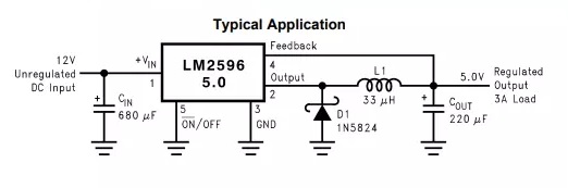
- Input Capacitor: A ceramic or electrolytic capacitor is connected between the Vin pin and the GND pin of the LM2596 IC. This capacitor helps to smooth out any voltage spikes or transients on the input voltage, and also helps to reduce noise in the circuit.
- Output Capacitor: Another ceramic or electrolytic capacitor is connected between the Vout pin and the GND pin of the LM2596 IC. This capacitor helps to stabilize the output voltage and reduce any ripple or noise in the output.
- Inductor: An inductor is connected between the SW pin and the Vout pin of the LM2596 IC. The inductor helps to store and release energy to regulate the output voltage, and also acts as a filter to reduce ripple in the output.
- Diode: A Schottky diode is connected in parallel with the inductor, with the cathode connected to the Vout pin and the anode connected to the SW pin. The diode helps to conduct current from the inductor when the LM2596 switches off, preventing any voltage spikes that could damage the IC.
- Feedback Circuit: A voltage divider consisting of two resistors is connected between the Vout pin and the Adjust pin of the LM2596 IC. The feedback circuit provides a reference voltage to the IC, which it compares to the output voltage to regulate the output.
Library:
No code included.
Code:
No code included
Technical Details:
- Input voltage range: 4.5V to 35V
- Output voltage range: 1.3V to 30V (less than input)
- Maximum output current: 3A
- Switching frequency: 150KHz
- Output ripple: up to 50mV (maximum) over a 20M bandwidth
- Load regulation: ±0.5%
- Voltage regulation: ±2.5%
- Operating temperature range: -40 ℃ to +85 ℃.
- 48 * 23 * 14 mm
Resources:
Comparisons:
The LM2596 and LM317 are two different voltage regulator ICs that operate in different ways and are suited to different applications. Here are some of the main differences between the LM2596 and LM317:
- Step-Down vs. Linear Regulator: The LM2596 is a step-down switching regulator, which means that it takes a higher input voltage and outputs a lower, regulated voltage. The LM317, on the other hand, is a linear regulator, which means that it takes a higher input voltage and outputs a lower, regulated voltage by dissipating the excess voltage as heat.
- Efficiency: Because the LM2596 is a switching regulator, it is generally more efficient than the LM317, which dissipates excess voltage as heat. This means that the LM2596 is better suited to applications where efficiency is important, such as battery-powered devices or other applications where power consumption is a concern.
- Input Voltage Range: The LM2596 has a wider input voltage range than the LM317, which makes it better suited to applications where the input voltage may vary, such as in battery-powered devices or solar-powered systems.
- Output Current: The LM2596 can typically supply higher output currents than the LM317, which makes it better suited to applications where high output currents are required, such as in LED lighting systems or audio amplifiers.
- Circuit Complexity: The LM2596 is generally more complex to use than the LM317, as it requires additional components such as an inductor and a diode in addition to input and output capacitors. The LM317, on the other hand, requires only input and output capacitors, making it simpler to use in some applications.