AED 1.05
Description
The NPN C945 transistor is a commonly used bipolar junction transistor (BJT) that is designed for low-power amplifier and switching applications. The C945 transistor has a maximum collector current of 150mA, a maximum collector-emitter voltage of 50V, and a maximum power dissipation of 400mW. It is commonly used in small electronic projects, audio amplifiers, and voltage regulators.
Package Includes:
- 1 x NPN C945 transistor
Features:
- Widely used for low-power amplification and switching in electronic circuits.
- Has three terminals, namely the emitter, base, and collector.
- By applying a small current to the base terminal, the transistor allows a larger current to flow between the collector and emitter terminals.
- Suitable for use in a wide range of electronic projects, including small electronic projects, audio amplifiers, and voltage regulators.
- Offers a low noise figure and high gain, making it ideal for use in audio amplifier circuits.
- Fast switching speed makes it useful in switching applications.
- Has a small size and can be easily integrated into electronic circuits.
- Has a low cost, making it an economical choice for many applications.
Description:
The NPN C945 transistor is a type of bipolar junction transistor (BJT) that is widely used for low-power amplification and switching in electronic circuits. It has three terminals, namely the emitter, base, and collector. By applying a small current to the base terminal, the transistor allows a larger current to flow between the collector and emitter terminals. The maximum collector current that the C945 transistor can handle is 150mA, and it has a maximum collector-emitter voltage of 50V. The maximum power dissipation is 400mW, which means that it can handle up to 400 milliwatts of power without overheating. This type of transistor is commonly used in small electronic projects, audio amplifiers, and voltage regulators.
Principle of Work:
To understand how the NPN C945 transistor works, it is important to first understand its basic structure and operating principle.
- Structure: The C945 transistor is a type of bipolar junction transistor (BJT), which consists of three semiconductor regions: a thin p-type layer sandwiched between two n-type regions. These three regions are known as the emitter, base, and collector. The emitter is heavily doped, while the base is lightly doped, and the collector is moderately doped.
- Operating principle: The C945 transistor operates on the principle of current amplification through the use of a small current controlling a larger current. The base-emitter junction of the transistor is forward-biased, which means that a small current flowing into the base terminal causes a larger current to flow from the collector to the emitter. This current amplification is what makes the transistor useful for amplification and switching applications.
- When no current is applied to the base terminal, the transistor is in its "off" state, and no current flows through the collector and emitter. However, when a small current is applied to the base terminal, the transistor turns "on", allowing a larger current to flow from the collector to the emitter. The amount of current flowing through the transistor is controlled by the amount of current applied to the base terminal, which can be adjusted by changing the input signal or biasing the transistor with a voltage source.
- In amplification applications, the input signal is applied to the base terminal, causing a small current to flow through the transistor. This small current is amplified by the transistor, which allows a larger current to flow through the collector and emitter, resulting in an amplified output signal. In switching applications, the transistor is used to control the flow of current through a load by turning "on" or "off" in response to a control signal applied to the base terminal.
Pinout:
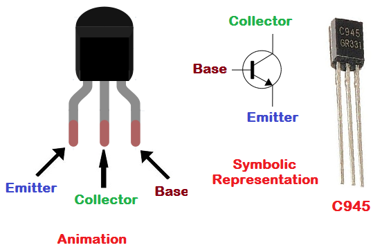
- The transistor has three pins: the emitter (E), base (B), and collector (C).
- The emitter is typically connected to the ground or negative terminal of the circuit.
- The collector is connected to the load or output of the circuit.
- The base is used to control the flow of current through the transistor and is usually connected to the input or control signal.
Applications:
- Low-power amplifier circuits: The C945 transistor is commonly used in small signal amplifier circuits, where it can be used to amplify low-level audio or radio frequency signals.
- Switching circuits: The transistor can also be used in switching circuits to control the flow of current to other components in the circuit. For example, it can be used to turn on and off a motor, LED, or relay.
- Voltage regulation: The C945 transistor can be used in voltage regulator circuits to regulate the voltage supplied to a load or output. This is often used in power supply circuits to ensure a stable and consistent output voltage.
- Oscillator circuits: The transistor can be used in oscillator circuits to generate a periodic waveform, such as a square wave or sine wave.
- Logic circuits: The transistor can be used in digital logic circuits as a switch to control the flow of current to other components, such as other transistors or LEDs.
- DIY electronics projects: Due to its low cost and availability, the C945 transistor is commonly used in DIY electronics projects, such as hobbyist circuits or educational projects.
Circuit:
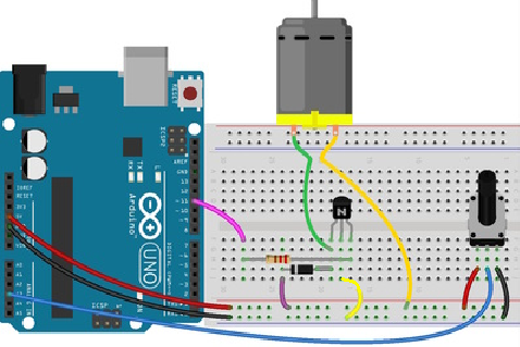
- A transistor (such as NPN C945) is connected between the motor and the 5V power supply, with the collector connected to the positive lead of the motor and the emitter connected to the ground The base of the transistor is connected to the digital pin 11 on the Arduino, through a current-limiting resistor (such as 1k ohms)
- Potentiometer connected to analog pin A3 on the Arduino
- The diode is connected to protect the transistor form the negative spikes of the motor.
Library:
No Library is needed.
Code:
an example code for controlling a motor using an Arduino and a transistor with the motor connected to pin 11, a potentiometer connected to A3 for speed control, and printing the PWM value on the serial monitor:
const int motorPin = 11;  // Motor control pin
const int potPin = A3;    // Potentiometer analog input pin

int potValue = 0;         // Variable to store potentiometer value
int motorSpeed = 0;       // Variable to store motor speed

void setup() {
  pinMode(motorPin, OUTPUT);   // Set motor pin as output
  Serial.begin(9600);          // Initialize serial communication
}

void loop() {
  potValue = analogRead(potPin);    // Read potentiometer value
  motorSpeed = map(potValue, 0, 1023, 0, 255);   // Map potentiometer value to motor speed

  analogWrite(motorPin, motorSpeed);   // Set motor speed using PWM

  Serial.print("Potentiometer Value: ");
  Serial.print(potValue);
  Serial.print(", Motor Speed: ");
  Serial.println(motorSpeed);
  delay(100);   // Delay for stability
}
- In this code, we use the
analogRead()function to read the value of the potentiometer connected to A3. Then, we use themap()function to scale the potentiometer value from 0-1023 to 0-255, which corresponds to the PWM value we need to set for the motor speed. - We then use the
analogWrite()function to set the motor speed using PWM on pin 11. Finally, we print the potentiometer value and motor speed to the serial monitor usingSerial.print()andSerial.println()functions.
Technical Details:
- Power dissipation=0.4W(Tamb=25°C).
- Collector current(Icm)=0.15A.
- Collector-base voltage(Vcbo)=60V.
- Operating and storage junction temp. range=-55 to 150°C.
- Material of Transistor: Si
- Polarity: NPN
- Maximum Collector Power Dissipation (Pc): 0.2 W
- Maximum Collector-Base Voltage |Vcb|: 60 V
- Maximum Collector-Emitter Voltage |Vce|: 50 V
- Maximum Emitter-Base Voltage |Veb|: 5 V
- Maximum Collector Current |Ic max|: 0.15 A
- Max. Operating Junction Temperature (Tj): 150 °C
- Transition Frequency (ft): 150 MHz
- Collector Capacitance (Cc): 3 pF
- Forward Current Transfer Ratio (hFE), MIN: 130
- Package: SOT23
Resources:
Comparisons:
The C945 and BC547 are both commonly used bipolar junction transistors (BJTs) that are designed for low-power amplifiers and switching applications. Here are some similarities and differences between the two:
Similarities:
- Both are NPN-type transistors.
- Both have three terminals: emitter, base, and collector.
- Both have similar maximum ratings for collector current and power dissipation.
- Both are widely available and commonly used in small electronic projects.
Differences:
- The C945 has a maximum collector-emitter voltage of 50V, while the BC547 has a maximum collector-emitter voltage of 45V.
- The C945 has a higher DC current gain (hFE) range than the BC547.
- The C945 has a different pinout than the BC547, so they cannot be used interchangeably without adjusting the wiring.
- The BC547 is generally considered to be a more modern transistor than the C945 and may be easier to find in some regions.
Both transistors are similar in their applications and performance but may have different ratings and pinouts that should be taken into account when choosing which one to use in a given circuit.