Out Of Stock
Description
The UNO is the most known and used development board, this is The UNO R3 SMD Compatible which copies every thin in the Arduino Uno with more features and makes use of a CH340 to communicate with the PC and upload sketches you can use an enormous number of boards called shields to extend your Uno board functionality and make your projects fast and easy and the implementation of the pin headers in the Uno board gives you the ability to connect everything using Dupont wires.
Package Includes:
- 1 x UNO R3 SMD Compatible Upgraded
Features:
- ATmega328 processor running at 16MHz
- CH340 Serial to USB converter
- 32KB Flash memory
- 14 Digital I/O
- 6 PWM shared with the digital I/O
- 6 Analog inputs that can also be used as digital I/O for a total of up to 20 digital I/O
- 1 Hardware serial port
- 5V Operation
Description:
The UNO is the most known and used development board, this is The UNO R3 SMD Compatible which copies every thin in the Arduino Uno with more features and makes use of a CH340 to communicate with the PC and upload sketches you can use an enormous number of boards called shields to extend your Uno board functionality and make your projects fast and easy and the implementation of the pin headers in the Uno board gives you the ability to connect everything using Dupont wires. This version of the board has a great feature in that, in addition to the standard female headers for bringing out I/O, each female header has a row of holes next to it that can be soldered male headers, a second row of female headers, or even wires. These can be soldered to the board's top or bottom side. the board comes with a strip of male headers that are normally soldered to the top side of the board. Because the separate sections of headers on one side are not spaced apart on 0.1′′, the board cannot be mounted directly into a breadboard if the male headers are soldered to the bottom of the board.
Principle of Work:
Uno is Free hardware which is anything whose blueprints and specs are available for anybody to copy. This means that Arduino provides the framework so that any other individual or business can design their own boards, each of which can be unique yet function well when built upon the same framework. Free software is a computer program whose source code is available to anybody, allowing them to use and alter it as they see fit. In order to allow anyone to create apps for Arduino boards and provide them with a variety of utilities, Uno works with the Arduino IDE (Integrated Development Environment) platform. which you can use to program and upload your code (sketch) and do this using an onboard Serial Converter with the help of an embedded bootloader you can easily do this without the need for any external programmer, the Uno uses libraries that can be downloaded online and gives you the ability to program a big number of sensor and module without even knowing how they really work.
Pinout of the Module:
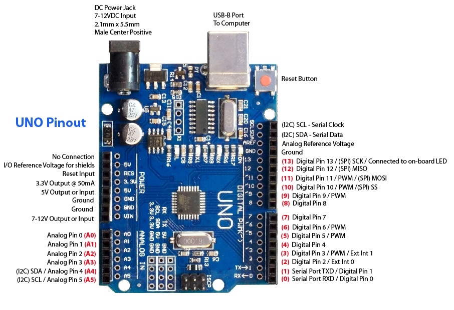
| Serial Communication Pin: |
Connect to serial communication. 4Pins (GND, VCC (3.3V or 5V controlled by slide switch), RX, TX)
|
| Ground: | Ground pins |
| V Pins (VCC): |
Power the external sensors and modules. Select the voltage of 3.3V or 5V via a slide switch.
|
| Digital I/O: |
It has 14 digital input/output pins, labeled D0 to D13 (of which 6 can be used as PWM outputs). These pins can be configured as digital input pins to read the logic value (0 or 1). Or used as a digital output pin to drive different modules like LED, relay, etc. The pin D3, D5, D6, D9, D10, and D11 can be used to generate PWM.
|
| Digital port: |
you can connect through female headers, or through pin headers (labeled S) of 2.54mm pitch.
|
| AREF: |
For Analog reference. Sometimes used to set an external reference voltage (0-5V) as the upper limit of analog input pins.
|
| SDA & SCL | IIC communication pin |
| ICSP (In-Circuit Serial Programming) Header: |
ICSP is an AVR, an Arduino micro-program header consisting of MOSI, MISO, SCK, RESET, VCC, and GND.
|
| Microcontroller: |
:Each control board has its own microcontroller. You can regard it as the brain of your board.
|
| The microcontroller used in this board: | ATMEGA328P-AU. |
| D13 LED: |
There is a built-in LED driven by digital pin 13. When the pin is HIGH value, the LED is on, when the pin is LOW, it's off.
|
| TX LED: |
Onboard you can find the label: TX (transmit) When the Arduino board communicates via the serial port and sends the message, TX led flashes.
|
| RX LED: |
Onboard you can find the label: RX(receive ) When the UNO board communicates via serial port and receives the message, RX led flashes.
|
| Power LED: | LED on means that your circuit board is correctly powered on. Otherwise, LED is off. |
| USB Connection: |
You can power the board via a USB connection. Or can upload the program to the board via a USB port. Connect the board to the PC using a USB cable via a USB port.
|
| ATMEGA 16U2-MU: | USB to serial chip, can convert the USB signal into the serial port signal. |
| Voltage regulator: |
control the voltage provided to the UNO board, as well as stabilizes the DC voltage used by the processor and other components. Convert an external input DC7-12V voltage into DC 5V, then switch DC 5V to the processor and other components, output DC 5V, drive current is 1A
|
| DC Power Jack | can be supplied with an external power DC7-12V from the DC power jack. |
| RESET Header | Connect an external button to reset the board. The function is the same as a reset button |
| Pin 3V3 Output | Provides 3.3V voltage output Pin 5V OutputProvides 5V voltage output |
| Vinny | can supply an external voltage input DC7-12V through this pin to the board. |
| Analog Pins: |
The UNO board has 6 analog inputs, labeled A0 through A5. Can also use as digital pins, A0=D14, A1=D15, A2=D16, A3=D17, A4=D18, A5=D19.
|
| Analog ports: |
, you can connect through female headers, or through pin headers (labeled S) of 2.54mm pitch.
|
| IIC Communication Pin: Connect | 4Pins (GND, VCC , SDA, SCL) |
| RESET Button: | You can reset your board to start the program from the initial status. |
Applications:
- Weighing Machines.
- Traffic Light Count Down Timer.
- Parking Lot Counter.
- Embedded systems.
- Home Automation.
- Industrial Automation.
- Medical Instrument.
- Emergency Light for Railways.
Circuit:
We will not need any circuit, in this testing code, we will rely on the built-in LED on the 13th pin.
Connecting with Arduino First Time
1. Open Arduino IDE
If you haven’t done so already, download Arduino IDE from the software page.
Arduino IDE
and now you need to download the CH340 Driver:
Follow this link instructions
unzip the file
2. Connect the board to your computer
Next, connect to board to your computer with a USB cable. This will both power the board and allow the IDE to send instructions to the board. You’ll need a data USB cable (a charge-only cable will not work), with connectors that fit both the board and your computer.
3. Select Board
Next, you need to tell Arduino IDE which board your sketch is for.
Click on Tools in the menu bar and find the Board row. If a board is currently selected it will be displayed here.
The tools menu with the Board row is highlighted.
Hover over the Board row to reveal the installed board packages. These packages contain some popular boards.
Click on a board to select it.
Selecting a board in Arduino IDE.
44. Select port
Click on Tools in the menu bar and find the Port row. If a board is currently selected it will be displayed here.
The tools menu with the Port row highlighted.
Hover over the Port to reveal all ports. For Arduino devices, the board name will typically be displayed after the port.
Port naming varies by system:
Windows: COM3 (Arduino Uno)
macOS: /dev/cu.usbmodem14101 (Arduino Uno)
Linux: /dev/ttyACM0 (Arduino Uno)
Click on a port to select it. If the port with your board is already selected you don’t have to do anything. If you don’t see your board in the list, see If your board does not appear in the port menu.
Selecting a port in Arduino IDE.
Troubleshooting: If you don’t see your board in the list, see If your board does not appear in the port menu.
5. Upload a sketch
Write a sketch, or use an Example such as Blink (File > Examples > 01. Basics > Blink).
Optional: Click the Verify button to try compiling the sketch and check for errors.
Click the Upload button to program the board with the sketch.
Your sketch will start running on the board. It will run again each time the board is reset.
Code:
void setup() {
pinMode(13,1);
}
void loop() {
digitalWrite(13,1);
delay(1000);
digitalWrite(13,0);
delay(1000);
}
Technical Details:
- Input voltage - 7-12V
- Operating Voltage: 5 Volt
- Input Voltage: 7 to 20 Volts (limits)
- DC Current per I/O Pin: 20 mA
- DC Current for 3.3V Pin: 50 mA
- Dimensions: 69mm x 53mm (approx)
Resources:
- You might also want to look at: the reference for the Arduino language;
Comparisons:
This board is very similar to the (Keyesturio UNO R3 Upgraded version) the SMD version has the CH340 which needs a third-party driver too and has a double pin header for every pin which gives you the ability to connect using female or male pins but keyestudio v pin has the ability to work with 5v and 3.3v by flipping the switch on board, the board and aside from the switch, the extra pins headers and the Serial converter which needs driver the board is compatible with all the codes and shields of the Arduino Uno R3 Board.