AED 11.55
Description
The ESP8266 WiFi Module is a SOC (System on Chip) with an integrated TCP/IP protocol stack, providing WiFi connectivity to any microcontroller. It can either host an application or offload Wi-Fi networking functions from another processor. Pre-programmed with an AT command set firmware, it offers easy integration with Arduino devices, akin to a WiFi Shield. With a vast community and cost-effectiveness, it's a popular choice for IoT projects.
Features:
- 802.11 b/g/n Support: The ESP8266 module supports 802.11 b/g/n standards, ensuring compatibility with most WiFi networks, both old and modern.
- Integrated Low-Power 32-bit MCU: Incorporating a low-power 32-bit microcontroller unit (MCU) enables efficient operation while conserving energy, making it suitable for battery-powered applications.
- Integrated 10-bit ADC: With an integrated 10-bit Analog-to-Digital Converter (ADC), the module can accurately measure analog signals, expanding its range of potential applications, especially those requiring sensor data acquisition.
- Integrated TCP/IP Protocol Stack: The TCP/IP protocol stack is built into the module, facilitating seamless communication over the Internet or local networks, and ensuring reliable data transmission.
- Integrated Components: The module integrates several essential components, including a TR switch, balun, low-noise amplifier (LNA), power amplifier, matching network, Phase-Locked Loop (PLL), regulators, and power management units. This integration streamlines the design process and reduces the need for external components.
- Supports Antenna Diversity: Antenna diversity support enhances signal reception by utilizing multiple antennas, improving the module's performance in challenging environments with signal interference or weak coverage.
- Supports WPA/WPA2 Security Protocols: Compatibility with WPA/WPA2 security protocols ensures secure communication over WiFi networks, safeguarding data transmission from unauthorized access or interception.
- Multiple Operation Modes: The module supports various operation modes, including Station (STA), Access Point (AP), and STA+AP modes, offering flexibility for different networking configurations and applications.
- Multiple Interfaces: The module features a range of interfaces, including SDIO 2.0, High-Speed Serial Peripheral Interface (SPI), Universal Asynchronous Receiver-Transmitter (UART), Inter-Integrated Circuit (I2C), Inter-IC Sound (I2S), Infrared Data Association (IRDA), Pulse Width Modulation (PWM), and General-Purpose Input/Output (GPIO), enabling versatile connectivity with external devices and peripherals.
Specifications:
- Supply Voltage: 3.3V
- Operating Temperature Range: -40°C to 125°C
- Deep Sleep Power: <10uA
- Power Down Leakage Current: <5uA
- Wake-up and Transmit Packet Time: <2ms
- Standby Power Consumption (DTIM3): <1.0mW
- Output Power in 802.11b Mode: +20dBm
- 1 x ESP8266 ESP-12E WiFi Module
Tutorial: Minimal Configuration for Running the ESP-12e Module
1. Understanding the ESP-12e Module:
- The ESP-12e module is an excellent choice for projects requiring multiple pin options and boasts 4MBytes of flash memory.
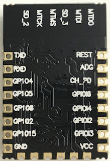
Image: ESP-12e Module
2. Unveiling the Oddities:
- While the ESP-12e is a powerful module, it comes with a few quirks:
- The silkscreen quality might not be perfect.
- The ADC pin is labeled as ADG.
- GPIO labeling might seem confusing, e.g., GPIO0 is labeled as GPIO6.
3. Basic Configuration Setup:
- Here's the most basic configuration you'll need:
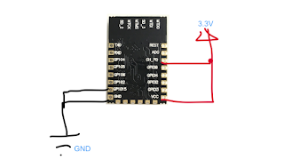
Image: Basic Configuration for ESP-12e
- Shorten GPIO15 to ground.
- Connect the "chip Power Down" Pin (ch_PD) to 3.3V.
4. Firmware Flashing:
- If you plan to program new firmware:
- Connect GPIO0 (labeled GPIO6) to ground to enter flashing mode.
- Consider using NodeMCU firmware for ease of use.

Image: Flashing Firmware on ESP-12e
5. Physical Connection:
- Connecting a serial-USB converter is straightforward:
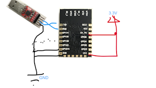
Image: Connecting the USB2Serial converter
- Follow the standard RXD-TXD / TXD-RXD connections.
- Don't forget to connect the ground wires for a complete setup.