AED 12.50
Description
The ACS712 Current Sensor 5A Version is a cutting-edge device designed for precise current measurement. With its advanced technology, this sensor provides accurate readings of up to 5 Amperes. The ACS712 is equipped with high-performance components and boasts exceptional noise rejection, ensuring reliable and stable measurements. Its compact and robust design allows for easy integration into various applications, from power supplies to motor control systems. This sensor also features a user-friendly interface, making it accessible to both professionals and hobbyists.
Package Includes:
- 1x ACS712 Current Sensor Module 5A Version
Features:
- Chip: ACS712ELC-05B 5V This is the chip on that the sensor module is based. It is a Hall effect sensor that can measure both positive and negative currents up to 30A.
- Operating voltage: The sensor module requires a 5VDC power supply to operate.
- Operating voltage with LED: Pin 5V power supply, on-board power indicator, The sensor module has an on-board power indicator LED that lights up when the module is powered on.
- Current range: The sensor module can measure currents from +30A to -30A.
- Analog output: The sensor module outputs an analog voltage that is proportional to the current that is being measured. The output voltage is 185mV/A.
- No test current through the output voltage: When there is no current flowing through the sensor module, the output voltage is VCC / 2.
- The low-noise analog signal path The sensor module has a low-noise analog signal path that minimizes noise and distortion in the output signal.
- Device bandwidth is set via the new FILTER pin The bandwidth of the sensor module can be set by connecting a resistor to the FILTER pin.
- Stable output offset voltage The output offset voltage of the sensor module is stable, which means that the output voltage does not drift over time.
- Near zero magnetic hysteresis The sensor module has near zero magnetic hystereses, which means that the output voltage is not affected by the polarity of the current that is being measured.
- High DC PSRR enables use with low-accuracy power supplies or batteries (3 to 4.5 V operation) The sensor module has a high DC PSRR, which means that it can be used with low-accuracy power supplies or batteries. The module can operate with a voltage of 3 to 4.5 V.
Description:
The sensor module is a small, lightweight, and affordable device that can be used to measure current in electrical circuits. It is based on the ACS712ELC-05B 5V chip, which is a Hall effect sensor that can measure both positive and negative currents up to 30A. The sensor module has an onboard power indicator LED and outputs an analog voltage that is proportional to the current that is being measured. The output voltage is 185mV/A. The sensor module has a low-noise analog signal path, a stable output offset voltage, near-zero magnetic hysteresis, and a high DC PSRR. It can be used with low-accuracy power supplies or batteries (3 to 4.5 V operation).The sensor module has an on-board power indicator LED that lights up when the module is powered on.The sensor module is easy to install and use, and it can be used for a variety of applications, including monitoring current in electrical circuits, measuring the power consumption of devices, detecting faults in electrical systems, and controlling the flow of current.
Principle of Work:
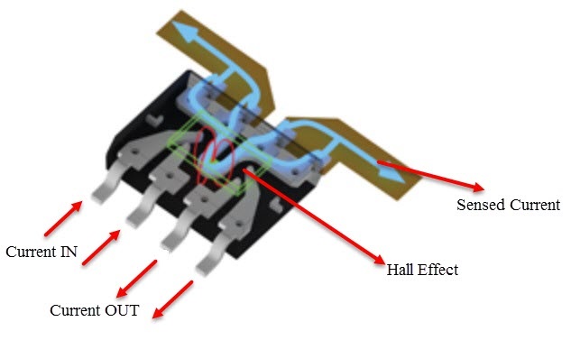
The ACS712 module has a Hall Effect sensor that is located on a copper conduction path. When current flows through the copper conduction path, it creates a magnetic field. The Hall Effect sensor detects this magnetic field and converts it into an analog voltage. The output voltage is proportional to the current that is flowing through the conductor.
The ACS712 module also has a number of other components, including:
- Reference voltage: The reference voltage is used to calibrate the Hall Effect sensor. The reference voltage is typically provided by a 5V power supply.
- Amplifier: The amplifier amplifies the output signal from the Hall Effect sensor. The amplifier is necessary to increase the output voltage to a level that can be easily measured by other devices.
- Filter: The filter removes noise from the output signal. The filter is necessary to improve the accuracy of the current measurement.
- Output buffer: The output buffer provides a high-impedance output for connecting to other devices. The output buffer prevents the current from flowing back into the ACS712 module.
|
ACS712 Model |
Optimized Current Range |
Output Sensitivity |
|
ACS712 ELC-05
|
+/- 5A
|
185mV/A |
Pinout of the Board:

The ACS712 module has a simple pinout that makes it easy to connect to other devices. The VCC and GND pins are connected to the power supply, and the OUT pin is connected to the input of an ADC or other device that can measure analog voltages:
- The VCC pin can be connected to a 5V power supply or a 3V battery.
- The GND pin can be connected to the negative terminal of the power supply or to a common ground.
- The OUT pin can be connected to the input of an ADC, a microcontroller, or another device that can measure analog voltages.
Applications:
- Power supply monitoring: The ACS712 module can be used to monitor the current draw of a power supply by connecting the module to the power supply's output. The output voltage of the module will be proportional to the current draw of the power supply. This information can be used to prevent overloads and to ensure that the power supply is operating within its specifications.
- Motor control: The ACS712 module can be used to control the speed and direction of a motor by connecting the module to the motor's power supply. The output voltage of the module will be proportional to the current draw of the motor. This information can be used to control the motor's speed and direction.
- Battery monitoring: The ACS712 module can be used to monitor the battery level of a device by connecting the module to the battery's terminals. The output voltage of the module will be proportional to the current draw of the battery. This information can be used to prevent the device from running out of power and to ensure that the battery is operating within its specifications.
- Fault detection: The ACS712 module can be used to detect faults in electrical circuits by connecting the module to the circuit. The output voltage of the module will be proportional to the current draw of the circuit. Sudden changes in current can indicate a fault in the circuit.
- Electrical load detection and management: The ACS712 module can be used to detect and manage electrical loads. This can be used to prevent the overloading of electrical circuits and to ensure that electrical loads are operating within their specifications.
- Switched-mode power supplies (SMPS): The ACS712 module can be used in switched-mode power supplies (SMPS). SMPS are used to convert AC power to DC power, and they are commonly used in electronic devices. The ACS712 module can be used to monitor the current draw of an SMPS and to ensure that the SMPS is operating within its specifications.
- Protection for over-current: The ACS712 module can be used to protect electrical circuits from over-current. Over-current can damage electrical circuits, and the ACS712 module can be used to detect over-current and to shut down the circuit before damage occurs.
- Research and development: The ACS712 module can be used for research and development purposes by connecting the module to different devices or circuits. The output voltage of the module can be used to study the power consumption of different devices or to develop new methods for controlling motors.
Circuit:
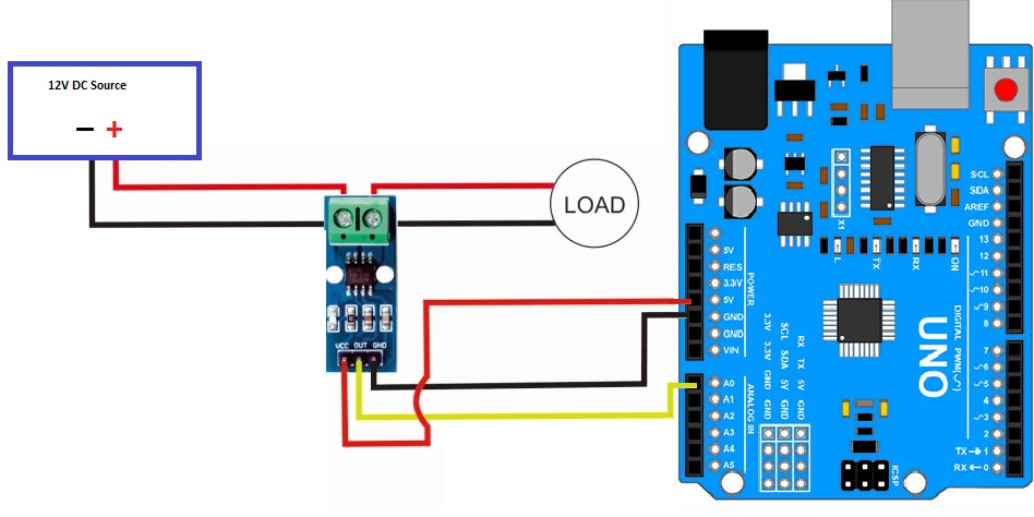
- 12V DC GND source: Connect the GND terminal of the 12V DC power supply to the GND terminal of the load.
- 12V DC VCC: Connect the VCC terminal of the 12V DC power supply to the current terminal of the module. The other terminal of the current terminal should be connected to the VCC input of the load.
- VCC of the Module: Connect the VCC pin of the module to the 5V pin of the Arduino.
- GND of the Module: Connect the GND pin of the module to the GND pin of the Arduino.
- OUT of the Module: Connect the OUT pin of the module to the A0 pin of the Arduino.
The 12V DC power supply provides power to the load and the module. The VCC pin of the module is connected to the 5V pin of the Arduino so that the module can be powered. The GND pin of the module is connected to the GND pin of the Arduino to provide a common ground for the two devices. The OUT pin of the module is connected to the A0 pin of the Arduino so that the Arduino can read the output voltage of the module, which is proportional to the current flowing through the load.
Library:
here are the steps on how to add the ACS712 library to Arduino IDE:
- Go to the ACS712 library repository.
- Click the Clone or download button and select Download ZIP.
- Extract the ZIP file to a folder on your computer.
- Open the Arduino IDE.
- Go to Sketch > Include Library > Add .ZIP Library.
- Select the ZIP file that you extracted in Step 3.
- The ACS712 library will be added to your Arduino IDE.
Once the ACS712 library is added to your Arduino IDE, you can start using it in your sketches.
Code:
The code is used to measure the current flowing through a circuit. The code uses the ACS712 current sensor to measure the current. The ACS712 current sensor is a Hall Effect sensor that can measure currents up to 5 Amperes:
#include "ACS712.h"

ACS712 sensor(ACS712_05B, A0);

void setup() {
  Serial.begin(9600);
  sensor.calibrate();
}

void loop() {
  float current = sensor.getCurrentAC();

  // Ignoring the value below 0.09
  if (current < 0.09) {
    current = 0;
  }

  Serial.println(current);
  delay(300);
}
- The code first includes the
ACS712.hlibrary. This library provides the functions that are needed to interface with the ACS712 current sensor. - Next, the code creates an instance of the
ACS712class. TheACS712class provides the functions that are needed to read the current from the sensor. - The
setup()function initializes the serial port and calibrates the sensor. Thecalibrate()function sets the zero point of the sensor. This is necessary to ensure that the sensor is accurate. - The
loop()function reads the current from the sensor and prints the value to the serial port. Thedelay()function pauses the execution of the code for 300 milliseconds. This is done to prevent the serial port from being overwhelmed with data. - The
ifstatement checks if the current is below 0.09. If it is, then the value ofcurrentis set to 0. Otherwise, the valuecurrentis not changed. - The
Serial.println()function prints the value ofcurrentthe serial port. The serial port can be connected to a computer so that the value of the current can be viewed on the computer. - The
delay()function pauses the execution of the code for 300 milliseconds. This is done to prevent the serial port from being overwhelmed with data. - The code will continue to run in a loop, reading the current from the sensor and printing the value to the serial port.
Technical Details:
- Measuring range ± 5A / DC
- Analog output 185 mV/A
- no current flows - output voltage is ~ VCC / 2
- 1.2 mΩ internal conductor resistance
- Total output error of 1.5% at TA = 25°C
- 80kHz bandwidth
- Dimensions PCB: L x W x H approx. 27.5 x 11.6 x 14 mm
Resources:
Comparisons:
The ACS712 is a popular current sensor that is available in three variants: ACS712ELC-05, ACS712ELC-20, and ACS712ELC-30. These variants differ in their optimized current ranges, output sensitivity, and resolutions.
- Optimized current range: The optimized current range is the range of currents that the sensor is most accurate at measuring. The ACS712ELC-05 is optimized for measuring currents up to +/-5A, the ACS712ELC-20 is optimized for measuring currents up to +/-20A, and the ACS712ELC-30 is optimized for measuring currents up to +/-30A.
- Output sensitivity: The output sensitivity is the amount of voltage that is generated by the sensor for a given current. The ACS712ELC-05 has an output sensitivity of 185 mV/A, the ACS712ELC-20 has an output sensitivity of 100 mV/A, and the ACS712ELC-30 has an output sensitivity of 66 mV/A.
- Resolution: The resolution is the smallest change in current that the sensor can accurately measure. The resolution is inversely proportional to the output sensitivity. The ACS712ELC-05 has a resolution of 0.32 mA, the ACS712ELC-20 has a resolution of 0.5 mA, and the ACS712ELC-30 has a resolution of 0.83 mA.
The ACS712 is a versatile current sensor that can be used in a variety of applications. The choice of which variant to use depends on the specific application requirements. For example, if you need to measure currents up to +/-5A with high resolution, then the ACS712ELC-05 is a good choice. If you need to measure currents up to +/-30A with less resolution, then the ACS712ELC-30 is a good choice.
| Optimized current range | Output sensitivity | Resolution |
|---|---|---|
| +/-5A | 185 mV/A | 0.32 mA |
| +/-20A | 100 mV/A | 0.5 mA |
| +/-30A | 66 mV/A | 0.83 mA |