Out Of Stock
Description
The 7-segment Digital LED Display 1 Digit CC is a compact and versatile display unit. It features a single digit with a common cathode configuration, making it suitable for a wide range of applications. The emitted color is red, providing clear and visible output. With a pin count of 10 and a pin pitch of 2mm/0.08", it offers easy integration and connectivity. The display's size, excluding the pins, is 19 x 13 x 7mm (LWH), and the height of the digital 7-segment is 14.2mm/0.56"
Package Includes:
- 1 x 7-segment Digital LED Display 1 Digit CC
Features:
- Digit Configuration: It features a single digit, allowing you to display numbers from 0 to 9 or other symbols.
- Common Cathode: The display adopts a common cathode configuration, where the cathode of all the LED segments is connected together. This simplifies the wiring and control of the display.
- Emitted Color: The LED display emits red light, which offers good visibility and readability in various lighting conditions.
- Pin Count: It has a total of 10 pins, which provide connection points for power supply and segment control.
- Pin Pitch: The pin pitch of 2mm/0.08" ensures easy integration and compatibility with standard breadboards, connectors, or soldering techniques.
- Size: The display size, excluding the pins, is 19 x 13 x 7mm (LWH). This compact size makes it suitable for applications where space is limited.
- Digital 7-Segment Height: The height of each digit on the 7-segment display is 14.2mm/0.56". This ensures clear and legible characters.
- LED Color: The LEDs used in the display are red in color, providing a consistent and vibrant output.
- Net Weight: The display unit weighs approximately 22g, making it lightweight and easy to handle.
Description:
The LD-5161 is a highly versatile and reliable 7-segment Digital LED Display 1 Digit CC. This display unit is meticulously designed to meet your digital visualization needs with precision and clarity. Equipped with a single digit and employing a common cathode configuration, the LD-5161 offers seamless integration into your electronic projects. Its common cathode design simplifies the wiring process and enables easy control of individual segments, ensuring a hassle-free experience. Featuring a captivating red emitted color, this LED display guarantees exceptional visibility in various lighting conditions. Whether you're displaying numeric values, symbols, or other characters, the vivid red glow delivers enhanced legibility and makes your content stand out effortlessly. The LD-5161 boasts 10 carefully positioned pins, providing convenient connection points for seamless power supply and segment control. With a pin pitch of 2mm/0.08", it effortlessly aligns with standard breadboards, connectors, and soldering techniques, allowing for effortless integration into your existing setups. Measuring at a compact size of 19 x 13 x 7mm (LWH) excluding the pins, this LED display saves valuable real estate in your projects while delivering impressive performance. The digital 7-segment height of 14.2mm/0.56" ensures the legibility of characters, making it suitable for both close-up and distant viewing. Crafted with precision and attention to detail, the LD-5161 LED display guarantees reliability and durability. Despite its powerful performance, it remains lightweight, weighing approximately 22g, making it ideal for portable applications or projects where weight is a concern.
Principle of Work:
The 7-segment Digital LED Display 1 Digit CC (LD-5161) works by utilizing a combination of individual light-emitting diodes (LEDs) arranged in a specific pattern to form numeric or alphanumeric characters:
- Common Cathode Configuration: The LD-5161 features a common cathode configuration. This means that all the cathodes of the individual LEDs in each segment of the display are connected together. The common cathode is typically connected to the ground or negative terminal of the power supply.
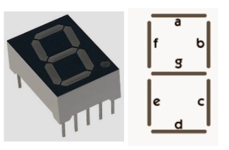
- Segments and Pins: The display consists of seven segments (labeled as a, b, c, d, e, f, and g) that form the shapes necessary to display numbers or characters. In addition to the seven segments, there is an additional eighth segment, often referred to as the dot or decimal point.
- Control Pins: The LD-5161 has 10 pins. The eight pins (a to g and dot) are used to control the individual segments, while the remaining two pins are for the common cathode connection.
- Multiplexing: To display different numbers or characters, the LD-5161 utilizes a technique called multiplexing. This involves quickly cycling through each segment of the display, one at a time, while maintaining persistence of vision. By rapidly switching between segments, it creates the illusion of all the segments being lit simultaneously.
- Segment Control: To illuminate a specific segment, the corresponding control pin is driven with a voltage. When a control pin receives a high signal, the associated segment LED turns on, and the segment becomes visible.
- Digit Control: Since the LD-5161 is a 1-digit display, it can only display one number or character at a time. To display multiple digits, multiple display units can be connected together and controlled simultaneously.
- Interfacing: To control the LD-5161, you would typically connect the control pins of the display to a microcontroller or a dedicated display driver circuit. The microcontroller or driver circuit provides the necessary signals to activate the desired segments and control the overall display output.
Pinout of the Module:
- Pin 1: Dot (Decimal Point)
- Pin 2: Segment a
- Pin 3: Segment b
- Pin 4: Segment c
- Pin 5: Segment d
- Pin 6: Segment e
- Pin 7: Segment f
- Pin 8: Segment g
- Pin 9: Common Cathode
- Pin 10: Common Cathode
Please note that this pinout assumes a left-to-right orientation when viewing the display from the front, with the pins facing down.
Applications:
- Digital Clocks: The LD-5161 can be used to create digital clock displays, showing hours and minutes.
- Counters and Timers: It can be employed in counters or timers to display the elapsed time, countdowns, or event counts.
- Measurement Devices: The display can be utilized in measurement instruments such as multimeters, voltmeters, or frequency counters to present readings or values.
- Industrial Control Panels: It is suitable for industrial control panels where numeric or alphanumeric data needs to be displayed, such as in process control systems or manufacturing equipment.
- Scoreboards: The LD-5161 can be used in sports scoreboards or game displays to show scores, time, or other relevant information.
- Instrumentation: It can be integrated into various instruments and devices, including temperature controllers, pH meters, or pressure gauges, to provide clear and readable output.
- Educational Projects: The display is commonly used in educational projects to demonstrate numeric operations, digital logic, or basic microcontroller programming.
- Consumer Electronics: It can be found in consumer electronics devices such as calculators, digital watches, or small electronic gadgets.
Circuit:
Arduino Connections:
- Connect the common cathode pins (pin 9 and pin 10) of the LD-5161 display to the GND (ground) pin on the Arduino board.
- Connect the segment pins (pin 2 to pin 8) of the LD-5161 display to digital output pins on the Arduino pins respectively.
- you should use a resistor of 220ohm between every LED pin and the Arduino Output pin
Library:
No library needed
Code:
An example of how you can connect the LD-5161 7-segment display to an Arduino board and a sample code to display numbers:
// Pin mapping for segments (a-g) on the LD-5161 display
int segments[] = {2, 3, 4, 5, 6, 7, 8};

void setup() {
  // Set the segment pins as outputs
  for (int i = 0; i < 7; i++) {
    pinMode(segments[i], OUTPUT);
  }
}

void loop() {
  // Display numbers 0 to 9 repeatedly
  for (int num = 0; num < 10; num++) {
    displayNumber(num);
    delay(1000);  // Adjust the delay as needed
  }
}

void displayNumber(int num) {
  // Define segment patterns for numbers 0 to 9
  byte numberPatterns[] = {
    B11111100,  // 0
    B01100000,  // 1
    B11011010,  // 2
    B11110010,  // 3
    B01100110,  // 4
    B10110110,  // 5
    B10111110,  // 6
    B11100000,  // 7
    B11111110,  // 8
    B11110110   // 9
  };

  // Display the number by turning on/off appropriate segments
  for (int i = 0; i < 7; i++) {
    digitalWrite(segments[i], bitRead(numberPatterns[num], i));
  }
}
- Pin Mapping: The code begins by defining an array called
segmentsthat represents the Arduino pins connected to the segments (a to g) of the LD-5161 display. Each element of the array corresponds to a segment pin. - Setup Function: In the
setup()function, the segment pins are configured as output pins using thepinMode()function. This ensures that the Arduino can control the display segments. - Loop Function: The
loop()function is where the main code execution takes place. In this example, it continuously displays numbers 0 to 9 on the 7-segment display. - Display Number Function: The
displayNumber()function is defined to display a specific number on the LD-5161 display. It takes an argumentnum, which represents the number to be displayed. - Number Patterns: Inside the
displayNumber()function, there is an array callednumberPatternsthat holds the binary patterns for each number from 0 to 9. Each binary pattern represents which segments need to be turned on or off to display the corresponding number. - Segment Control: Using a
forloop, the code iterates through the segment pins (from pin 2 to pin 8) and sets their state (HIGH or LOW) based on the corresponding bit value in thenumberPatternsarray. ThebitRead()function is used to extract the state of each segment from the binary pattern. - Looping through Numbers: In the
loop()function, anotherforloop is used to display numbers from 0 to 9 repeatedly. It calls thedisplayNumber()function with the current number and then delays for a specified duration (in this case, 1000 milliseconds or 1 second) using thedelay()function. You can adjust the delay value to control the display speed.
Technical Details:
- Product Name: LED Digital display
- Model: LD-5161
- Type: Common Cathode
- Emitted Color: Red;
- Pin Number: 10;
- Pin Pitch: 2mm/0.08"
- Size(Not Including Pins) : 19 x 13 x 7mm (L*W*H);
- Digital 7Seg Height: 14.2mm/0.56"
- Color of LED: red
- Net Weight: 22g;
Resources:
Comparisons:
The main difference between the 7-segment Digital LED Display 1 Digit CC (Common Cathode) and the 7-segment Digital LED Display 1 Digit CA (Common Anode) lies in their electrical characteristics and how they are controlled. Here's a comparison of using these two types of displays:
-
Electrical Connection:
- CC (Common Cathode): In this configuration, the cathodes of all the individual LEDs within each segment are connected together and common to the ground or negative terminal of the power supply.
- CA (Common Anode): In this configuration, the anodes of all the individual LEDs within each segment are connected together and common to the positive terminal of the power supply.
-
Control Voltage:
- CC: To turn on a specific segment, a high voltage or logic level is applied to the corresponding control pin, which is connected to the common cathode.
- CA: To turn on a specific segment, a low voltage or logic level is applied to the corresponding control pin, which is connected to the common anode.
-
Segment Illumination:
- CC: When a segment's control pin receives a high signal, the associated LED segment connected to the common cathode is turned on, resulting in illumination.
- CA: When a segment's control pin receives a low signal, the associated LED segment connected to the common anode is turned on, resulting in illumination.
-
Driving Circuitry:
- CC: To control the display, the microcontroller or driver circuit needs to sink current to the segments by providing a low signal to the corresponding control pins.
- CA: To control the display, the microcontroller or driver circuit needs to source current to the segments by providing a high signal to the corresponding control pins.
-
Compatibility:
- CC: Common cathode displays are commonly used in applications where the driving circuitry is designed to sink current, such as some microcontrollers and driver ICs.
- CA: Common anode displays are commonly used in applications where the driving circuitry is designed to source current, such as some shift registers or driver ICs.