AED 36.75
Description
The LCD 20x4 Character Display Module is a display device that can show up to 20 characters per line and up to 4 lines of text. It has a yellow background and uses the popular HD44780 controller chip. This module is commonly used in embedded systems and microcontroller projects to display information such as sensor readings, messages, and menu options. It operates on a low voltage and has a simple interface, making it easy to use with various microcontrollers and other electronic devices.
Package Includes:
- 1 x LCD 20x4 Character Display Module
Features:
- Display: The module can display up to 20 characters per line and up to 4 lines of text, with a yellow background and black characters for good visibility.
- Controller: The module uses the popular HD44780 controller chip, which provides a simple and well-documented interface between the display module and the controlling device.
- Voltage: The module operates on a low voltage of typically 5V, which makes it suitable for use with a wide range of microcontrollers and other electronic devices.
- Interface: The module requires a minimum of 6 data pins to communicate with the controlling device, which makes it easy to interface with a variety of microcontrollers and other electronic devices.
- Character generator: The module has a built-in character generator that can display a variety of characters and symbols, making it a versatile display option.
- Simple graphics: In addition to text display, the module can also be used for simple graphics and animations, such as scrolling text or progress bars.
- Durability: The module is a durable and reliable display option, making it suitable for use in a variety of different applications.
Description:
The LCD 20x4 Character Display Module is a popular type of alphanumeric display that can show up to 20 characters per line and up to 4 lines of text. It is typically used in embedded systems and microcontroller projects to display various types of information, such as sensor readings, messages, and menu options. This display module has a yellow background, which provides good contrast and visibility for the text displayed on the screen. It uses the HD44780 controller chip, which is a widely used and well-documented controller for LCD displays. This chip provides a simple interface between the display module and the microcontroller or other electronic device that is controlling it. The module operates on a low voltage, typically 5V, and requires a minimum of 6 data pins to communicate with the controlling device. It also has a built-in character generator that can display a variety of characters and symbols, making it a versatile display option.
In addition to its primary use as a text display, the LCD 20x4 Character Display Module can also be used for simple graphics and animations, such as scrolling text or progress bars. It is a durable and reliable display option, making it a popular choice for many different types of electronic projects.
Principle of Work:
The working principle of the LCD 20x4 Character Display Module is based on the physical properties of liquid crystals. The module contains a layer of liquid crystal material sandwiched between two polarizing filters. When an electric current is applied to the liquid crystal layer, it changes the orientation of the crystals, which in turn affects the amount of light that is able to pass through the polarizing filters. The HD44780 controller chip is responsible for controlling the operation of the LCD module. It sends commands and data to the module, which are then interpreted by the module's internal circuitry to display the desired characters or graphics on the screen. To display characters on the screen, the controller chip sends a series of commands to the module to set the cursor position, select the appropriate character or symbol from the built-in character generator, and display it on the screen. This process is repeated for each character in the message to be displayed.
The driver for the HD44780 controller chip typically consists of a library of software functions that can be called by the controlling device, such as a microcontroller, to communicate with the LCD module. The driver provides a simple and standardized interface between the controlling device and the LCD module, making it easy to use with a wide range of electronic devices.
Pinout of the Module:

- VSS: Ground pin
- VDD: Power supply pin (typically 5V)
- V0: LCD contrast adjustment pin
- RS: Register select pin - selects whether data or command is being sent
- RW: Read/Write pin - selects whether data is being written to or read from the module
- E: Enable pin - enables the module to receive data or commands
- D0: Data pin 0 - least significant bit of the data bus
- D1: Data pin 1
- D2: Data pin 2
- D3: Data pin 3
- D4: Data pin 4
- D5: Data pin 5
- D6: Data pin 6
- D7: Data pin 7 - most significant bit of the data bus
- A: Backlight Anode
- K: Backlight Cathode
Applications:
The LCD 20x4 Character Display Module has a wide range of applications in electronics and embedded systems. Some common applications include:
- Data monitoring and display: The module can be used to display real-time data, such as temperature, pressure, and other sensor readings.
- User interface: The module can be used to display menu options, prompts, and other user interface elements in embedded systems and consumer electronics.
- Control panels: The module can be used in control panels for industrial equipment, automotive systems, and other applications.
- Test equipment: The module can be used in test equipment to display test results, measurement readings, and other data.
- DIY projects: The module can be used in hobbyist and DIY projects, such as building a custom alarm clock or a home automation system.
- Robotics: The module can be used in robotics projects to display sensor readings, motor control status, and other data.
- Education: The module can be used in educational settings to teach electronics and embedded systems programming.
Circuit:
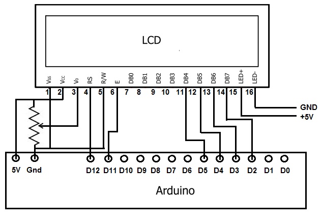
the connections for the LCD display:
- RS pin of the LCD display is connected to pin 12 of the Arduino board.
- EN pin of the LCD display is connected to pin 11 of the Arduino board.
- D4 pin of the LCD display is connected to pin 5 of the Arduino board.
- D5 pin of the LCD display is connected to pin 4 of the Arduino board.
- D6 pin of the LCD display is connected to pin 3 of the Arduino board.
- D7 pin of the LCD display is connected to pin 2 of the Arduino board.
Library:
No library installation needed
Code:
An Arduino program that communicates with an LCD display and a computer via serial communication:
#include "LiquidCrystal.h"

// initialize the library by associating any needed LCD interface pin
// with the arduino pin number it is connected to
const int rs = 12, en = 11, d4 = 5, d5 = 4, d6 = 3, d7 = 2;
LiquidCrystal lcd(rs, en, d4, d5, d6, d7);

void setup() {
  // set up the LCD's number of columns and rows:
  lcd.begin(20, 4);
  // Print a message to the LCD.
  lcd.print("LCD Initialized");
  Serial.begin(9600);
  while (!Serial) {
    ; // wait for serial port to connect. Needed for native USB port only
  }
}

void loop() {
  if (Serial.available()) {
    String input = Serial.readString();
    lcd.clear();
    lcd.setCursor(0, 0);
    lcd.print("Received: ");
    lcd.print(input);
  }
}
The LiquidCrystal library is used to control the LCD display. The pins that are connected to the LCD display are declared at the beginning of the code. In the setup() function, the LCD display is initialized with its dimensions and a message is printed to the display. The Serial.begin(9600) function initializes the serial communication with the computer at a baud rate of 9600.
In the loop() function, the code waits for a serial input from the computer. When a serial input is available, it is read as a String. The LCD display is then cleared and the received string is printed on the display. This process is repeated continuously as long as the program is running.
Technical Details:
| LCD Name | 4x20 Character LCD Display 20 x 4 Matrix LCD Module With Yellow Backlight | ||
|
Display Format |
20character*4 line |
Display Mode |
STN (gray), Positive,Transflective |
|
LCD Color |
Display dot: Black Background: Yellow |
Surface Treatment |
Anti-glare |
|
Outline Dimension |
98.0(W) x60(H) x 14.2MAX(T)mm |
Viewing Area |
76MIN(W) x25.8MIN(H)mm |
|
Viewing Direction |
6 O’clock |
Interface Input Data |
4-bit or 8-bit MPU interface enabled |
|
Backlight |
Yellow |
Driving Method |
1/16 Duty, 1/5 Bias |
|
Operating Temp. |
-20℃~+70℃ |
Storage Temp. |
-30℃~+80℃ |
Resources:
Comparisons:
The LCD display module can be interfaced with Arduino using two different methods:
- Direct connection using individual pins
- Indirect connection using an I2C module
The differences between the two methods:
- Wiring: When using the LCD display module with individual pins, several wires are required to connect the LCD display to the Arduino board. On the other hand, when using the I2C module, only two wires (SDA and SCL) are required to interface the LCD display with the Arduino board.
- The number of pins required: The LCD display module with individual pins requires at least 6 pins on the Arduino board to function properly. This can be a disadvantage when using an Arduino board with limited pins. On the other hand, the I2C module requires only 2 pins, which saves a lot of pins on the Arduino board.
- Ease of use: The I2C module simplifies the process of interfacing the LCD display with the Arduino board as it provides a simple and easy-to-use interface. It also saves time as it eliminates the need for complex wiring.