AED 13.25
Description
The NRF24L01 is a wireless RF network IoT module that operates at 2.4GHz frequency. It is a low-cost, low-power device that can communicate with other NRF24L01 modules over a distance of up to 100 meters in open space. The module uses the Enhanced ShockBurst protocol for efficient and reliable data transmission and has a maximum data rate of 2Mbps. It can be used in a variety of applications, such as wireless sensor networks, home automation, remote control, and Internet of Things (IoT) devices. The module is easy to use, with a simple interface and minimal external components required for operation.
Package Includes:
- 1 x NRF24L01 is a wireless RF network IoT module
Features:
- Operating frequency: The module operates on the 2.4GHz frequency band, which is a license-free band available in many countries around the world.
- Data rate: The module has a maximum data rate of 2Mbps, making it suitable for high-speed data transfer applications.
- Range: The module can operate over a distance of up to 100 meters in open space, and can be extended further with the use of external antennas.
- Power consumption: The module is designed to operate in low-power modes to conserve energy, and supports various power-saving features such as automatic standby mode.
- Enhanced ShockBurst protocol: The module uses the Enhanced ShockBurst protocol for efficient and reliable data transmission. This protocol supports the automatic retransmission of lost packets and dynamic channel selection for improved reliability and performance.
- Simple interface: The module has a simple interface that can be controlled using a few GPIO pins, and requires only a few external components to operate.
- Low-cost: The module is low-cost, making it an attractive option for hobbyists, makers, and designers who want to add wireless connectivity to their projects without having to deal with complex wireless protocols.
- Multi-purpose: The module can be used in a variety of applications, such as wireless sensor networks, home automation, remote control, and Internet of Things (IoT) devices.
- Easy to use: The module is easy to use, with a simple interface and minimal external components required for operation.
- Flexible power levels: The module supports a range of power levels, from -18dBm to 0dBm, to optimize the transmission range and power consumption.
Description:
The NRF24L01 is a popular wireless RF network IoT module that uses the 2.4GHz frequency band for communication. It is designed for low-cost, low-power wireless applications, making it ideal for use in IoT devices, wireless sensor networks, and other low-power applications. The module uses a proprietary protocol called Enhanced ShockBurst to ensure efficient and reliable data transmission. This protocol supports the automatic retransmission of lost packets and dynamic channel selection for improved reliability and performance. The module also supports a range of power levels, from -18dBm to 0dBm, to optimize the transmission range and power consumption. The NRF24L01 module has a maximum data rate of 2Mbps, making it suitable for applications that require high-speed data transfer. It can operate over a distance of up to 100 meters in open space, and even further with the use of external antennas. One of the key advantages of the NRF24L01 module is its ease of use. It has a simple interface that can be controlled using a few GPIO pins and requires only a few external components to operate. This makes it an attractive option for hobbyists, makers, and designers who want to add wireless connectivity to their projects without having to deal with complex wireless protocols. In terms of power consumption, the NRF24L01 is designed to operate in low-power modes to conserve energy. It also supports various power-saving features, such as automatic standby mode, to further reduce power consumption.
Principle of Work:
The NRF24L01 module uses a proprietary protocol called Enhanced ShockBurst for wireless communication. The module contains a transmitter and a receiver, and data is transmitted between the two devices using radio waves at a frequency of 2.4GHz. The transmitter sends data packets to the receiver, which uses a built-in protocol engine to receive and process the packets. The protocol engine checks the integrity of the received data and automatically requests the retransmission of any lost packets. The module also supports dynamic channel selection, which allows the devices to change channels automatically in the event of interference or noise on the current channel. The module has a simple interface that can be controlled using a few GPIO pins. It requires only a few external components to operate, including a power supply, a microcontroller or other control device, and an antenna. The NRF24L01 module supports a range of power levels, from -18dBm to 0dBm, to optimize the transmission range and power consumption. The module is also designed to operate in low-power modes to conserve energy, and supports various power-saving features such as automatic standby mode.
Pinout of the Module:
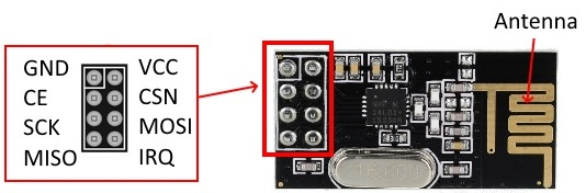
| Pin Name | Pin Number | Function |
|---|---|---|
| VCC | 1 | Power supply, 1.9V to 3.6V |
| CE | 2 | Chip enable |
| CSN | 3 | Chip select |
| SCK | 4 | SPI clock |
| MOSI | 5 | SPI master out, slave in |
| MISO | 6 | SPI master in, slave out |
| IRQ | 7 | Interrupt request |
| GND | 8 | Ground |
- VCC: This pin is used to supply power to the NRF24L01 module. It requires a voltage supply of 1.9V to 3.6V.
- CE: This pin is used to enable the module for data transmission or reception. When this pin is set high, the module becomes active and starts transmitting or receiving data.
- CSN: This pin is used to select the module for SPI communication. When this pin is set low, the module becomes active and is ready to communicate with the microcontroller.
- SCK: This pin is the SPI clock signal that synchronizes data transmission between the microcontroller and the module.
- MOSI: This pin is the SPI master output and slave input, and is used to send data from the microcontroller to the module.
- MISO: This pin is the SPI master input and slave output, and is used to receive data from the module to the microcontroller.
- IRQ: This pin is an interrupt request that is used to signal the microcontroller when a data transmission or reception is complete.
- GND: This pin is the ground pin and is connected to the ground of the microcontroller.
The NRF24L01 module uses SPI communication to exchange data with the microcontroller. The CE pin is used to enable the module for data transmission or reception, and the CSN pin is used to select the module for SPI communication. The SCK, MOSI, and MISO pins are used for SPI communication between the module and the microcontroller. The IRQ pin is used to signal the microcontroller when a data transmission or reception is complete.
Applications:
- Wireless sensor networks: The NRF24L01 module can be used to create wireless sensor networks for various applications, such as environmental monitoring, home automation, and industrial control.
- Internet of Things (IoT) devices: The module can be used to add wireless connectivity to IoT devices, such as smart home appliances, wearable devices, and remote monitoring systems.
- Remote control: The module can be used for wireless remote control applications, such as controlling drones, robots, and other devices.
- Wireless audio: The module can be used for wireless audio applications, such as wireless headphones, wireless speakers, and other wireless audio devices.
- Industrial automation: The module can be used in industrial automation applications, such as monitoring and controlling machinery, and other industrial processes.
- Wireless data transfer: The module can be used for wireless data transfer applications, such as data logging, telemetry, and other wireless data transfer applications.
- Home automation: The module can be used in home automation applications, such as controlling lighting, heating, and other household appliances.
Circuit:
Both the transmitter and receiver use the same connections for the NRF24L01+ wireless module:
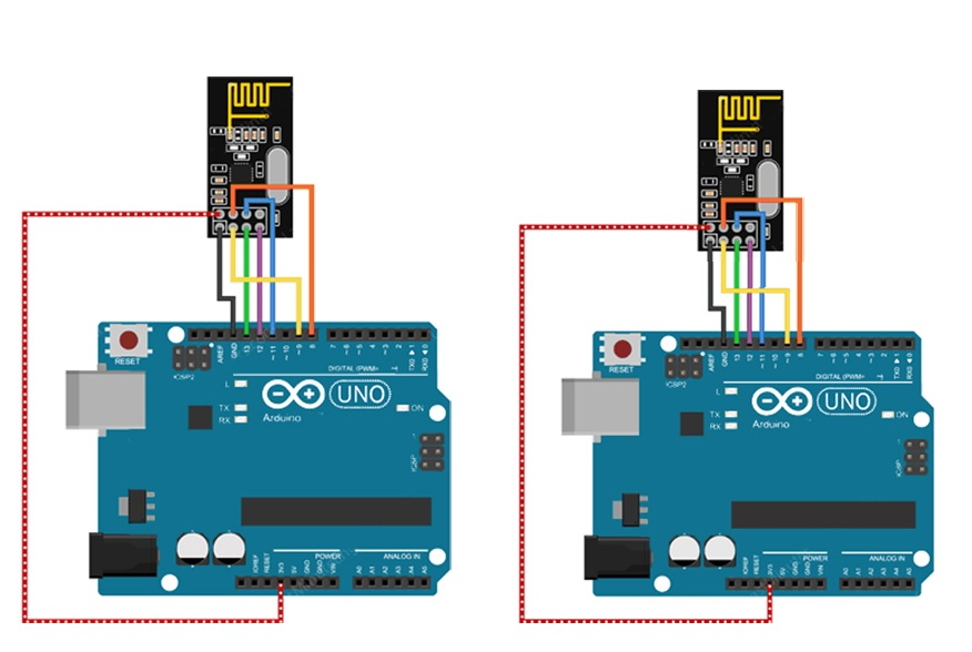
Arduino Pin - NRF24L01+ Wireless Module Pin
- D8 - CSN
- D9 - CE
- D11 - MOSI
- D12 - MISO
- D13 - SCK
- GND - GND
- 3V3 - VCC
Note that the NRF24L01+ module can be powered with either 3.3V or 5V, but it is recommended to use 3.3V to avoid damaging the module. If you use 5V, you should use a voltage regulator to lower the voltage to 3.3V before connecting it to the module. Also, make sure to use level shifters if you're using an Arduino board that operates at 5V to connect to the NRF24L01+ module to avoid damaging it.
Library:
To install the RF24 library on the Arduino IDE, follow these steps:
- Go to the official RF24 library repository on GitHub: https://github.com/nRF24/RF24
- Click the green "Code" button and select "Download ZIP" to download the library as a zip file.
- Open the Arduino IDE and go to "Sketch" -> "Include Library" -> "Add .ZIP Library..."
- Navigate to the downloaded zip file and select it.
- The library should now be installed and ready to use in your Arduino sketches.
Code:
Implementing a simple wireless communication system between two NRF24L01 modules using the RF24 library. The transmitter sends a message to the receiver, and the receiver reads the message and prints it to the serial monitor.
Transmitter Code:
//Include Libraries
#include "SPI.h"
#include "nRF24L01.h"
#include "RF24.h"

//create an RF24 object
RF24 radio(9, 8);  // CE, CSN

//address through which two modules communicate.
const byte address[6] = "00001";

void setup()
{
  radio.begin();

  //set the address
  radio.openWritingPipe(address);

  //Set module as transmitter
  radio.stopListening();
}
void loop()
{
  //Send message to receiver
  const char text[] = "Hello World";
  radio.write(&text, sizeof(text));

  delay(1000);
}
- It includes the necessary libraries (SPI.h, nRF24L01.h, and RF24.h) to control the NRF24L01 module.
- It creates an RF24 object and sets the CE and CSN pins to 9 and 8 respectively.
- It defines an address through which the transmitter and receiver will communicate.
- In the setup() function, the NRF24L01 module is initialized and the address is set for writing (openWritingPipe).
- In the loop() function, the message "Hello World" is sent to the receiver using the write() function of the radio object. The message is delayed for one second before being sent again.
Receiver Code
//Include Libraries
#include "SPI.h"
#include "nRF24L01.h"
#include "RF24.h"

//create an RF24 object
RF24 radio(9, 8);  // CE, CSN

//address through which two modules communicate.
const byte address[6] = "00001";

void setup()
{
  while (!Serial);
    Serial.begin(9600);

  radio.begin();

  //set the address
  radio.openReadingPipe(0, address);

  //Set module as receiver
  radio.startListening();
}

void loop()
{
  //Read the data if available in buffer
  if (radio.available())
  {
    char text[32] = {0};
    radio.read(&text, sizeof(text));
    Serial.println(text);
  }
}
- It includes the necessary libraries (SPI.h, nRF24L01.h, and RF24.h) to control the NRF24L01 module.
- It creates an RF24 object and sets the CE and CSN pins to 9 and 8 respectively.
- It defines an address through which the transmitter and receiver will communicate.
- In the setup() function, the NRF24L01 module is initialized, the address is set for reading (openReadingPipe), and serial communication is started.
- In the loop() function, the receiver waits for data to become available in the NRF24L01 module buffer using the available() function. Once data is available, it is read from the buffer using the read() function and printed to the serial monitor using the Serial.println() function.
Technical Specifications:
- Frequency: 2.4GHz ISM band
- Modulation: GFSK (Gaussian Frequency Shift Keying)
- Data rates: 250Kbps, 1Mbps, and 2Mbps
- Output power: -18dBm to 0dBm, software selectable
- Sensitivity: -82dBm at 2Mbps, -85dBm at 1Mbps, -88dBm at 250Kbps
- Maximum range: Up to 100 meters in open space
- Antenna: PCB antenna
- Operating voltage: 1.9V to 3.6V
- Current consumption: 13.5mA (transmit mode), 13.5mA (receive mode), 900nA (power down mode)
- Dimensions: 15.24mm x 29.05mm x 2.35mm
- Pin count: 8
- Pin spacing: 2.54mm (0.1 inch)
- Data interface: SPI (Serial Peripheral Interface)
- Operating temperature: -40°C to +85°C
Comparisons:
The main difference between the NRF24L01 2.4GHz Wireless RF Network IoT Module with an onboard antenna and the NRF24L01 2.4GHz Wireless RF Network IoT Module with LNA SMA external board is the antenna configuration. Here's a comparison between the two modules:
NRF24L01+ with onboard antenna:
- Comes with an onboard PCB antenna that is compact and easy to use.
- The onboard antenna provides a reasonable range of up to 100 meters in open space.
- It is a low-cost solution that is suitable for most IoT applications where space is limited.
NRF24L01+ with LNA SMA external board:
- Comes with an external antenna connector (SMA) and an LNA (Low Noise Amplifier) that can improve the range and sensitivity of the module.
- The external antenna allows for more flexible placement and can achieve longer range than the onboard antenna.
- The LNA helps to amplify weak signals, which can improve the sensitivity and reliability of the wireless link.
- However, the external antenna and LNA increase the size and cost of the module, and may require additional tuning to achieve optimal performance.