AED 15.00
Description
The ACS712 is an advanced current sensor module designed to accurately and efficiently detect both alternating current (AC) and direct current (DC) signals. It utilizes the highly reliable ACS712ELC-30 chip, which incorporates the Hall effect principle for precise current measurement. Equipped with an onboard power indicator, this module provides convenient visual feedback to indicate its operational status. It operates at a voltage of 5V, ensuring compatibility with various electronic systems and making it easily integrable into a wide range of projects. With its reliable performance and ability to discern both AC and DC currents, the ACS712 current sensor module is an ideal choice for applications that require accurate and real-time current monitoring, such as power management systems, industrial automation, renewable energy projects, and more.
Package Includes:
- 1x ACS712 Current Sensor 30A Version
Features:
- Chip: ACS712ELC-30A 5V
- Operating Voltage: 5VDC (can be powered from a microcontroller or other 5V power source)
- LED Indicator: The module features an onboard power indicator that provides visual feedback of its operational status.
- Current Measurement Range: The module can measure positive and negative currents up to 30 amps. The analog output corresponds to 66mV per ampere of current.
- Output Voltage: When no test current is passing through the module, the output voltage is VCC/2, providing a convenient reference point for zero current.
- Low-Noise Analog Signal Path: The ACS712 module incorporates a low-noise analog signal path, ensuring accurate and reliable current measurements.
- Adjustable Bandwidth: The device bandwidth can be set using the new FILTER pin, allowing flexibility in optimizing the module's performance for different applications.
- Stable Output Offset Voltage: The module maintains a stable output offset voltage, enhancing accuracy and precision in current measurements.
- Minimal Magnetic Hysteresis: The ACS712 exhibits near-zero magnetic hysteresis, minimizing the impact of magnetic fields on the accuracy of current readings.
- High DC Power Supply Rejection Ratio (PSRR): The module's high DC PSRR enables its use with low-accuracy power supplies or batteries, making it suitable for applications that operate within a voltage range of 3 to 4.5 volts.
Description:
The ACS712 is a highly reliable current sensor module that utilizes the ACS712ELC-30 chip, incorporating advanced Hall effect technology. This sensor module excels in accurately detecting both alternating current (AC) and direct current (DC) signals. It operates efficiently at a voltage of 5V, making it compatible with a wide range of electronic systems. One of the standout features of the ACS712 module is its analog output of 66mV per ampere (66mV/A), providing a linear relationship between the measured current and the generated voltage. This characteristic enables precise current measurement and monitoring in various applications. The sensor can measure positive and negative currents up to 30 amps, offering a wide dynamic range for current sensing needs. By leveraging the Hall effect principle, the ACS712 generates a voltage linearly proportional to the magnetic field it produces when current passes through it. This attribute not only ensures accurate current measurements but also allows for a linear response to the current flowing through the sensor. Consequently, it provides reliable and consistent results across different current levels. In addition to its exceptional functionality, the ACS712 module features an onboard power indicator that provides visual feedback regarding its operational status. This indicator enhances user convenience and allows for easy monitoring of the module's functionality.
Principle of Work:
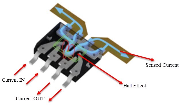
The ACS712 current sensor module operates based on the Hall Effect principle, which allows it to accurately measure the current flowing through a conductor. Let's dive into a more in-depth explanation of the internal chip and how the module functions as a whole:
-
Internal Chip: The ACS712 module is built around the ACS712ELC-30 chip, which is specifically designed for current sensing applications. The chip incorporates various components that work together to enable accurate current measurement:
a. Copper Conductor: Inside the chip, a copper strip connects the IP+ (positive current) and IP- (negative current) pins. This copper conductor acts as the pathway for the current to flow through.
b. Magnetic Field Creation: When current passes through the copper conductor, it generates a magnetic field around it. The strength of this magnetic field is directly proportional to the current magnitude.
c. Hall Effect Sensor: The ACS712 chip incorporates a Hall Effect sensor, which is a solid-state device that can detect and measure magnetic fields. The sensor is positioned in close proximity to the copper conductor.
d. Voltage Conversion: The Hall Effect sensor detects the magnetic field generated by the current flowing through the copper conductor. It then converts this magnetic field into a corresponding voltage signal.
-
Working Principle: The ACS712 module separates the input and output sections to ensure safety and accurate measurement:
a. Input Section: The input section of the module includes the IP+ and IP- pins. These pins are connected to the copper conductor within the ACS712 chip. When current passes through the copper conductor, a magnetic field is produced.
b. Hall Effect Detection: The Hall Effect sensor inside the ACS712 chip detects the magnetic field generated by the current flowing through the copper conductor. The sensor output is proportional to the strength of the magnetic field.
c. Voltage Output: The detected magnetic field is converted into a corresponding voltage signal by the Hall Effect sensor. The output voltage is directly proportional to the current passing through the module. In the ACS712ELC-30 model, the output sensitivity is 66 mV per ampere (66 mV/A).
d. Output Section: The converted voltage signal is made available at the OUT pin of the module. This analog output can be directly connected to an analog-to-digital converter (ADC) or read by a microcontroller for further processing.
Pinout of the Board:

ACS712 module has 3 pins as below:
- VCC: Power supply – 5 Volt
- GND: Ground
- OUT: Module output which is in the form of analog voltage.
Applications:
- Power Management Systems: The ACS712 module is widely used in power management systems to monitor and control the flow of current in electrical circuits. It allows for precise measurements of current consumption, enabling efficient energy management and optimization of power distribution.
- Motor Control: The module is employed in motor control applications, such as robotics and industrial automation. By monitoring the current flowing through motors, it enables precise control and protection against overloading or abnormal operating conditions.
- Energy Monitoring: The ACS712 module is utilized in energy monitoring systems to track and analyze the energy consumption of devices or systems. It enables accurate measurement of current flow, helping in energy conservation and load balancing.
- Battery Management: In battery-powered systems, the ACS712 module plays a vital role in monitoring the current drawn from or supplied to the battery. It assists in battery charging, discharging, and overall management, contributing to extended battery life and optimal performance.
- Solar Power Systems: The module is used in solar power systems to monitor the current generated by solar panels and the current flow in the charging and discharging processes. This aids in tracking the efficiency of solar energy conversion and managing the power flow in the system.
- Uninterruptible Power Supplies (UPS): UPS systems rely on the ACS712 module for monitoring the current during normal operation and detecting any abnormalities or overload conditions. It helps protect critical equipment and ensures the efficient functioning of the backup power supply.
- Automotive Electronics: The module is employed in automotive applications to measure current flow in various electrical systems, such as battery charging, lighting, motor control, and more. It aids in diagnostics, ensuring the proper functioning and safety of automotive electronics.
- Renewable Energy Systems: The ACS712 module is utilized in renewable energy systems, including wind and hydroelectric power systems, to measure and monitor current flow in the power generation and distribution processes. It assists in optimizing energy production and maintaining system stability.
- Industrial Control Systems: The module is integrated into industrial control systems for the current monitoring of machinery, equipment, and production lines. It enables precise measurement of current, ensuring operational safety and efficiency.
Circuit:
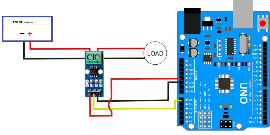
To measure the current flowing from a 12V power supply to a 12V DC lamp, the following wiring diagram is used:
- Connect the GND (ground) of the 12V DC power supply to the GND of the lamp (load).
- Connect the VCC (positive voltage) of the 12V DC power supply to one terminal of the current module. The other terminal of the current module is connected to the VCC input of the lamp.
- Connect the VCC of the current module to the 5V pin of the Arduino.
- Connect the GND of the current module to the GND pin of the Arduino.
- Connect the OUT pin of the current module to the A0 pin of the Arduino.
By following this wiring configuration, you will be able to measure the current flowing through the circuit accurately using the ACS712 current sensor module in conjunction with an Arduino board.
Library:
To install the ACS712 library in the Arduino IDE, you can follow these steps:
- Download the ACS712 library: You can download the ACS712 library here
- Open the Arduino IDE: Launch the Arduino IDE on your computer.
- Install the library: Go to "Sketch" in the Arduino IDE menu, then navigate to "Include Library" and click on "Add .ZIP Library".
- Select the downloaded library: Locate the downloaded ACS712 library file (in .zip format) on your computer and select it.
- Library installation: The Arduino IDE will automatically install the library. Once the installation is complete, you will see a confirmation message in the Arduino IDE.
Code:
The example code enables real-time monitoring of current passing through the sensor., it uses the ACS712 library to measure current with the ACS712 sensor module. It establishes serial communication and calibrates the sensor. In the main loop, it reads the current value, ignores values below a threshold, and prints the adjusted current value to the Serial Monitor.
#include "ACS712.h"

ACS712 sensor(ACS712_30A, A0);

void setup() {
  Serial.begin(9600);
  sensor.calibrate();
}

void loop() {
  float current = sensor.getCurrentAC();

  // Ignore small values to eliminate noise or offset
  const float threshold = 0.09;
  if (current < threshold) {
    current = 0;
  }

  // Print the current value to the serial monitor
  Serial.println(current);

  // Delay before the next reading
  const unsigned int delayTime = 300;
  delay(delayTime);
}
- The code begins with the inclusion of the required ACS712 library and the creation of an ACS712 object named
sensorwith the specified parameters (ACS712_30A and A0 pin). - In the
setup()function, the serial communication is initiated at a baud rate of 9600, and thesensor.calibrate()function is called to perform calibration for accurate measurements. - In the
loop()function:- The
getCurrentAC()function is used to obtain the AC current value from the sensor and store it in thecurrentvariable of typefloat. - A threshold value of 0.09 is set to determine the lower limit for valid current readings. If the current value is below this threshold, it is considered noise or offset and is set to 0.
- The adjusted current value is then printed to the serial monitor using
Serial.println(). - A delay of 300 milliseconds is introduced before the next reading using the
delay()function.
- The
Technical Details:
- Measuring range ± 30A / DC
- Analog output 66mV / A
- no current flows - output voltage is ~ VCC / 2
- 1.2 mΩ internal conductor resistance
- Total output error of 1.5% at TA = 25°C
- 80kHz bandwidth
- 66 to 185 mV/A output sensitivity
- Dimensions PCB: L x W x H approx. 27.5 x 11.6 x 14 mm
Resources:
Comparisons:
The ACS712 Sensor comes in three variants, each optimized for a different current sensing range: +/-5A, +/-20A, and +/-30A. While all three variants use the same IC, they differ in their configuration. When selecting a variant, it's important to consider the trade-off between the current range and resolution. If you need to measure higher currents, you will sacrifice some resolution compared to the lower current range variants.
this is a comparison of the three ACS712 variants:
-
ACS712 ELC-05:
- Optimized Current Range: +/- 5A
- Output Sensitivity: 185 mV/A
-
ACS712 ELC-20:
- Optimized Current Range: +/- 20A
- Output Sensitivity: 100 mV/A
-
ACS712 ELC-30:
- Optimized Current Range: +/- 30A
- Output Sensitivity: 66 mV/A
The output sensitivity indicates how much voltage the sensor generates per unit of current. A higher sensitivity means a greater change in output voltage for the same change in current. Therefore, the output sensitivity decreases as the optimized current range increases. When choosing an ACS712 variant, consider the specific current range you need to measure and the desired resolution for your application.