AED 16.50
Description
The Wireless Transmitter and Receiver Modules 315MHz RF Kit includes a transmitter and receiver module for remote control systems. Operating at 315 MHz, the square-shaped module is the transmitter and all are compatible with Arduino, with a voltage range of 3.5V to 12V DC and a maximum transfer rate of 4KB/S. It has a transmission distance of up to 3 meters, extendable to 5 meters with antennas. The receiver operates at the same frequency, with an operating voltage of 4.75V to 5.25V DC and a low current of 4mA, suitable for DIY projects requiring wireless communication.
Package Includes:
- 1 x Wireless Transmitter and Receiver Modules 315Mhz RF Kit
Features:
- Compact and square-shaped module designed for easy integration and space-saving applications.
- Compatible with Arduino, allowing seamless integration with Arduino-based projects and facilitating programming and control.
- Operating frequency of 315 MHz, making it suitable for various wireless communication applications.
- Wide working voltage range of 3.5V to 12V DC, providing flexibility in power supply options and accommodating a range of voltage sources.
- Maximum transfer rate of 4KB/S, enabling efficient and reliable transmission of data or control signals.
- Transmission distance of up to 3 meters (5 meters with additional antennas), allowing for wireless communication within a moderate range.
- Improved transmission distance with higher supply voltage, providing the option to extend the range based on power requirements.
- Well-suited for remote control systems such as rolling gates, smart cars, and smart homes.
- Ideal for DIY projects and hobbyist applications, enabling wireless communication integration with ease.
Description:
The Wireless Transmitter and Receiver Modules 315MHz RF Kit is a package that includes a transmitter module and a receiver module. These modules operate at a frequency of 315 MHz and are commonly used for remote control systems such as rolling gates, smart cars, and smart homes. The transmitter module, which has a square shape, is compatible with Arduino and can be easily integrated with microcontroller-based projects. It requires a working voltage between 3.5V and 12V DC and operates at the 315 MHz frequency. The maximum transfer rate of the module is 4KB/S. Without any additional antenna, the transmission distance can reach up to 3 meters when powered by a 5V DC supply. However, by soldering spring antennas to both the transmitter and receiver modules, the transmission distance can be extended up to 5 meters. It is important to note that the transmission distance increases with a higher supply voltage. The receiver module, on the other hand, has a rectangular shape and operates at the same 315 MHz frequency as the transmitter module. It requires an operating voltage between 4.75V and 5.25V DC. The receiver module has a low silent current of 4mA, making it energy-efficient. It is well-suited for do-it-yourself (DIY) projects where wireless communication is needed.
Principle of Work:
The internal working of the Wireless Transmitter and Receiver Modules 315MHz RF Kit involves the utilization of radio frequency (RF) technology for wireless communication. The transmitter module consists of a circuit that takes input signals from an Arduino or other connected devices. These input signals are typically digital or analog signals that need to be transmitted wirelessly. The module includes an RF oscillator that generates an RF carrier signal at the designated frequency of 315 MHz. The input signals modulate this carrier signal, altering its characteristics to encode the information to be transmitted. The modulated signal is then amplified and transmitted through an antenna to propagate as radio waves. On the receiver module side, an antenna picks up the transmitted radio waves and converts them back into electrical signals. The receiver module contains a demodulator that extracts the modulated signal from the received radio waves. The demodulated signal is then processed and filtered to recover the originally transmitted information. The processed information is made available as output signals that can be further utilized by an Arduino or other microcontroller for further processing or control. When working with Arduino, the transmitter module can be connected to an Arduino board, typically through digital or analog input pins. The Arduino can then generate the appropriate signals to be transmitted. The receiver module is connected to another Arduino, where the received signals are processed and decoded. The decoded information can be used to trigger specific actions or control various components or devices connected to the receiving Arduino.
Pinout of the Module:
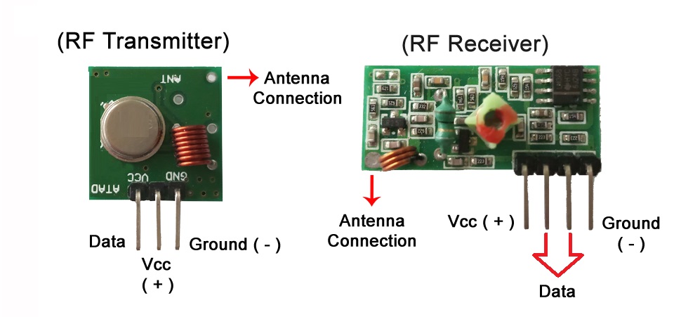
Wireless Receiver Module:
- VCC: Power supply voltage input (3.3V or 5V).
- DATA: Data input pin. Connect this pin to a microcontroller or any digital source to send data.
- DATA
- GND: Ground connection.
- ANT: Antenna connection. Connect an appropriate antenna to this pin for optimal transmission range.
Wireless Transmitter Module:
- DATA: Data output pin. Connect this pin to a microcontroller or any digital input to receive the transmitted data.
- VCC: Power supply voltage input (3.3V or 5V).
- GND: Ground connection.
- ANT: Antenna connection. Connect an appropriate antenna to this pin for optimal reception range.
Applications:
- Remote Control Systems: The modules can be used to create wireless remote control systems for operating devices such as remote-controlled cars, drones, home automation systems, and electronic appliances.
- Wireless Data Transmission: These modules can transmit and receive data wirelessly, making them suitable for applications such as wireless sensor networks, telemetry systems, weather stations, and industrial automation.
- Security Systems: The modules can be used in security systems to wirelessly transmit signals from sensors, such as door/window sensors, motion detectors, and smoke detectors, to a central control unit.
- Garage Door Openers: They can be utilized in garage door opener systems, where the transmitter module sends a signal to the receiver module to open or close the garage door.
- Wireless Alarms: The modules can be used in alarm systems to wirelessly transmit alarm signals, enabling communication between sensors and the alarm control panel.
- Remote Keyless Entry (RKE) Systems: They are commonly found in RKE systems for cars and vehicles, where the transmitter module is used in the key fob to send signals to the receiver module in the vehicle for locking, unlocking, and remote start functions.
- Wireless Audio Transmission: The modules can be used to transmit audio wirelessly from a source, such as a microphone or audio player, to a receiver for applications like wireless speakers, wireless headphones, or audio streaming systems.
- Hobbyist and DIY Projects: These modules are popular among hobbyists and electronics enthusiasts for DIY projects involving wireless communication, remote control, and data transmission.
Circuit:
Connect as you see in the schematic:

Library:
You have to install the VirtualWire library in your Arduino IDE:
You can install it by going to "Sketch" -> "Include Library" -> "Manage Libraries" and searching for "VirtualWire" by Mike McCauley.
Code:
An example code that demonstrates how to control an LED using a button and the 315MHz RF transmitter and receiver modules, connected to an Arduino UNO R3 This code sets up the transmitter to send the message "LED ON" when the button connected to pin 10 is pressed. The receiver listens for the message and turns on the LED connected to pin 3 when it receives the "LED ON" message.:
Transmitter Code:
#include "VirtualWire.h"

const int buttonPin = 10;
int buttonState = 0;

void setup() {
  pinMode(buttonPin, INPUT);
  vw_set_ptt_inverted(true);
  vw_setup(2000);
  Serial.begin(9600);
}

void loop() {
  buttonState = digitalRead(buttonPin);

  if (buttonState == HIGH) {
    const char *msg = "LED ON";
    vw_send((uint8_t *)msg, strlen(msg));
    vw_wait_tx();
    delay(200);
  }

  delay(50);
}
Receiver Code:
#include "VirtualWire.h"

const int ledPin = 3;

void setup() {
  pinMode(ledPin, OUTPUT);
  vw_set_ptt_inverted(true);
  vw_setup(2000);
  vw_rx_start();
  Serial.begin(9600);
}

void loop() {
  uint8_t buf[VW_MAX_MESSAGE_LEN];
  uint8_t buflen = VW_MAX_MESSAGE_LEN;

  if (vw_get_message(buf, &buflen)) {
    if (strcmp((char *)buf, "LED ON") == 0) {
      digitalWrite(ledPin, HIGH);
      delay(200);
    }
  }

  delay(50);
}
Transmitter Code Explanation:
#include: This line includes the VirtualWire library, which provides functions for wireless communication using RF modules.const int buttonPin = 10;: This line declares a constant integer variablebuttonPinand assigns it the value 10. This pin is connected to the button.int buttonState = 0;: This line declares an integer variablebuttonStateand initializes it to 0. It will be used to store the state of the button.void setup(): This is the setup function. It is called once when the Arduino is powered on or reset.pinMode(buttonPin, INPUT);: This line sets thebuttonPinas an input pin. This is where the button is connected.vw_set_ptt_inverted(true);: This line sets the PTT (Push-To-Talk) pin to be inverted. This is necessary for the VirtualWire library to work correctly.vw_setup(2000);: This line initializes the VirtualWire library with a data rate of 2000 bits per second. This should match the settings on the receiver side.Serial.begin(9600);: This line initializes the serial communication at a baud rate of 9600. This is used for debugging purposes and can be viewed in the Serial Monitor.void loop(): This is the loop function. It runs repeatedly after thesetup()function has finished executing.buttonState = digitalRead(buttonPin);: This line reads the state of the button connected tobuttonPinand stores it in thebuttonStatevariable.if (buttonState == HIGH): This line checks if the button is pressed (button state is HIGH).const char *msg = "LED ON";: This line declares a constant character pointermsgand assigns it the value "LED ON". This is the message that will be sent when the button is pressed.vw_send((uint8_t *)msg, strlen(msg));: This line sends the messagemsgusing the VirtualWire library. The message is converted to an array of bytes and sent wirelessly.vw_wait_tx();: This line waits for the transmission of the message to complete before moving on.delay(200);: This line adds a delay of 200 milliseconds to provide a small pause before sending another message. This helps to prevent multiple rapid transmissions if the button is held down.delay(50);: This line adds a delay of 50 milliseconds at the end of each iteration of the loop. This helps to reduce the processing load on the Arduino and allows other tasks to be performed.
ReceiverCode Explanation:
#include: This line includes the VirtualWire library, which provides functions for wireless communication using RF modules.const int ledPin = 3;: This line declares a constant integer variableledPinand assigns it the value 3. This pin is connected to an LED.void setup(): This is the setup function. It is called once when the Arduino is powered on or reset.pinMode(ledPin, OUTPUT);: This line sets theledPinas an output pin. This is where the LED is connected.vw_set_ptt_inverted(true);: This line sets the PTT (Push-To-Talk) pin to be inverted. This is necessary for the VirtualWire library to work correctly.vw_setup(2000);: This line initializes the VirtualWire library with a data rate of 2000 bits per second. This should match the settings on the transmitter side.vw_rx_start();: This line starts the VirtualWire library to receive incoming messages.Serial.begin(9600);: This line initializes the serial communication at a baud rate of 9600. This is used for debugging purposes and can be viewed in the Serial Monitor.void loop(): This is the loop function. It runs repeatedly after thesetup()function has finished executing.uint8_t buf[VW_MAX_MESSAGE_LEN];: This line declares an array of bytes namedbufwith a size ofVW_MAX_MESSAGE_LEN. This array is used to store the incoming message.uint8_t buflen = VW_MAX_MESSAGE_LEN;: This line declares an integer variablebuflenand assigns it the valueVW_MAX_MESSAGE_LEN. This variable is used to track the length of the incoming message.if (vw_get_message(buf, &buflen)): This line checks if a message has been received using the VirtualWire library. If a message is available, the condition evaluates to true.if (strcmp((char *)buf, "LED ON") == 0): This line compares the received message stored inbufwith the string "LED ON" using thestrcmp()function. If the two strings are equal, the condition evaluates to true.digitalWrite(ledPin, HIGH);: This line sets theledPinoutput to HIGH, turning on the LED.delay(200);: This line adds a delay of 200 milliseconds to keep the LED on for a short period.delay(50);: This line adds a delay of 50 milliseconds at the end of each iteration of the loop. This helps to reduce the processing load on the Arduino and allows other tasks to be performed.
Technical Details:
- Square-shaped module compatible with Arduino
- Operating frequency: 315 MHz
- Working voltage range: 3.5V to 12V DC
- Maximum transfer rate: 4KB/S
- Transmission distance: Up to 3 meters (5 meters with additional antennas)
- Increased transmission distance with higher supply voltage
Receiver Module Features:
- Rectangular-shaped module
- Operating frequency: 315 MHz
- Operating voltage range: 4.75V to 5.25V DC
- Low silent current: 4mA
- Suitable for DIY projects requiring wireless communication
Resources:
Comparisons:
The 315MHz RF transmitter and receiver modules and the 433MHz RF transmitter and receiver modules are both popular options for wireless communication. While they serve a similar purpose, there are a few key differences between them:
- Frequency: The most significant difference between these modules is the frequency at which they operate. The 315MHz modules operate at a frequency of 315MHz, while the 433MHz modules operate at 433MHz. This difference in frequency can affect the range, interference, and legal restrictions depending on the specific region and regulations.
- Range: The range of RF modules depends on various factors such as output power, antenna design, environment, and interference. In general, the 433MHz modules tend to have a slightly longer range compared to the 315MHz modules. This is because lower frequencies tend to have better propagation characteristics over longer distances.
- Interference: The choice of frequency can also impact the susceptibility to interference. In general, the 433MHz frequency range is more crowded and can be more susceptible to interference from other devices such as wireless routers, remote controls, or other nearby RF devices. The 315MHz frequency range may offer relatively fewer sources of interference in some environments.