AED 29.50
Description
The JoyStick Shield V1. A is an Arduino shield that features a cross PS2 joystick with buttons, including four round buttons and two small buttons. It allows for the extension of Arduino joystick and button input and can be used with various 3.3V microcontroller platforms. The shield has switches that can switch between 3.3V and 5V. It also includes interfaces for an NRF24L01 RF module, a Bluetooth module, a Nokia 5110 LCD, and I2C devices. The shield also includes a power switch to switch between 3.3V and 5V.
Package Includes:
- 1 x JoyStick Shield V1.A
Features:
- 2-axis joystick with proportional analog voltage on analog pin 0 for Y-axis movement and an analog signal on analog pin 1 for X-axis movement.
- joystick 'K' button is linked to D8.
- Six buttons labeled A-F on the board, with the four larger buttons often used for up/down/left/right or similar purposes, and the two smaller buttons utilized for less regularly used actions such as select or start.
- Pull-up resistors on all buttons that pull to the ground when pressed.
- NRF24L01 RF interface and Bluetooth module interface for wireless communication.
- The separate 4-pin female header for the Bluetooth interface, with RX/TX lines, 3.3V, and Ground.
- nRF24L01 interface connector that allows an nRF24L01 RF transceiver module to be plugged in, with a 2 x 4 female header for this interface that includes GND, VCC (3.3V), CE (connects to D9), CSN (connects to D10), SCK (connects to D13), MOSI (connects to D11), MISO (connects to D12), and IRQ (no connection).
- The Nokia 5110 LCD interface is designed to mount the Nokia 5110 LCD that provides a 48×84 pixel matrix. This interface occupies the same D9-D13 pins as the nRF24L01 and cannot be used at the same time as the nRF24L01 interface.
- I2C communication interface for easy connectivity to I2C devices, with the I2C SDA and SCL lines, as well as 5V and Ground, routed to a separate 4-pin male header in addition to the standard A4/A5 placement of these lines.
Description:
The JoyStick Shield V1.A is an Arduino-compatible shield that can be used to convert an Arduino Uno or a similar microcontroller board into a gaming console or a robotic controller. The shield features a cross PS2 joystick with buttons, including four round buttons and two smaller ones. It allows for the extension of Arduino joystick and button input, and onboard switches can switch between 3.3V and 5V, making it compatible with various 3.3V microcontroller platforms. The JoyStick Shield is a board that has a 2-axis joystick with an analog signal output for Y-axis and X-axis movement, and a 'K' button that is connected to D8. It also has six buttons, including four larger ones and two smaller ones, with pull-up resistors that pull to the ground when pressed. It allows easy connection to an NRF24L01 RF interface and a Bluetooth module interface, each with a separate connector. The board also has a Nokia 5110 LCD interface, which cannot be used simultaneously with the nRF24L01 interface since they occupy the same pins, and an I2C communication interface with a separate 4-pin male header for easy connectivity to I2C devices in addition to the standard A4/A5 placement of these lines.
Principle of Work:
The JoyStick Shield provides a simple and convenient interface for controlling an Arduino board with a joystick and buttons, as well as other external devices such as wireless communication modules and LCD displays. The shield is designed to be easily attached to an Arduino board, and the joystick and buttons can be used to provide input to the board for various applications, such as controlling a robot or playing games. The joystick produces analog voltages on two pins, which can be read by the Arduino's analog-to-digital converter to determine the joystick's position in two dimensions. The buttons are connected to digital pins, and when they are pressed, they can be detected by the Arduino through the use of internal pull-up resistors. The shield also provides easy connectivity to wireless communication modules such as the NRF24L01 and Bluetooth, as well as an LCD display through a separate interface. The use of standard communication protocols such as I2C further simplifies the process of connecting external devices to the Arduino board
- The 2-axis joystick produces a proportional analog voltage on analog pin 0 for Y-axis movement and an analog signal on analog pin 1 for X-axis movement. The joystick also has a 'K' button that can be accessed by pushing it down, which is linked to D8. In addition, there are six buttons labeled A-F on the board (not including the one on the joystick). The four larger buttons are often used for purposes such as up/down/left/right or similar, while the two smaller buttons are often utilized for less regularly used actions such as select or start. When pressed, all buttons feature pull-up resistors that pull to the ground.
- The NRF24L01 RF interface and The Bluetooth module interface for wireless communication. The RX/TX lines, as well as 3.3V and Ground, are routed to a separate 4-pin female header for the Bluetooth interface, which can be used to connect a Bluetooth 4-pin 3.3V device or a TTL serial device. The nRF24L01 interface connector allows an nRF24L01 RF transceiver module to be plugged in. The 2 x 4 female header for this interface includes GND, VCC (3.3V), CE (connects to D9), CSN (connects to D10), SCK (connects to D13), MOSI (connects to D11), MISO (connects to D12), and IRQ (no connection).
- The Nokia 5110 LCD interface, is designed to mount the Nokia 5110 LCD that was originally designed for Nokia phones and provides a 48×84 pixel matrix. This interface occupies the same D9-D13 pins as the nRF24L01, so it cannot be used at the same time as the nRF24L01 interface.
- The I2C communication interface for easy connectivity to I2C devices. The I2C SDA and SCL lines, as well as 5V and Ground, are routed to a separate 4-pin male header, which is in addition to the standard A4/A5 placement of these lines.
Pinout of the Module:
- Joystick:
- X-Axis potentiometer is linked to A0
- Y-Axis potentiometer is linked to A1
- The 'K' button is linked to D8
- Buttons:
- A-F buttons are present
- A-F buttons are linked to D2-D7
- All buttons have pull-up resistors that pull to ground
- Bluetooth Connector:
- RX/TX lines, 3.3V, and Ground are routed to a 4-pin female header
- Can be used to connect Bluetooth or TTL serial device
- I2C Connector:
- SDA and SCL lines, 5V, and Ground are routed to a 4-pin male header
- Allows easy attachment of I2C devices
- nRF24L01 Connector:
- GND, VCC, CE, CSN, SCK, MOSI, and MISO pins are present
- IRQ pin is not connected
- Nokia 5110 LCD Connector:
- Female header connector designed to mount Nokia 5110 LCD
- Provides a 48x84 pixel matrix
- Uses the same pins as nRF24L01, so cannot use both at the same time
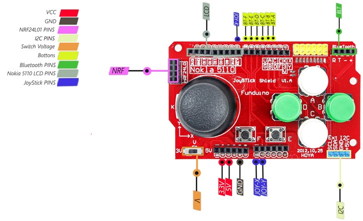
- Interface Connector:
- Dual row yellow male header connector
- Provides access to buttons, joystick pots, 3.3V, 5V, and Ground
- Pin-out is labeled on the board to the left of the connector
Applications:
- Gaming: The joystick and buttons can be used to create custom gaming controllers for various platforms.
- Robotics: The Shield can be used to control various robotic systems using the joystick and buttons.
- Wireless communication: The Shield supports Bluetooth and nRF24L01 RF transceiver modules, allowing for wireless communication between devices.
- LCD Display: The Shield can be used to display information on the Nokia 5110 LCD display.
- I2C devices: The Shield has a separate I2C header, allowing for easy connection of I2C devices.
- General purpose: The Shield provides easy access to all the pins on the Arduino board and can be used for general-purpose projects.
Circuit:
Just plug the shield in the Arduino Uno and you are good to go.

Library:
No need to download any library to work with this Shield unless you are going to use the rf module or the display.
Code:
example code that reads the values of each button and the joystick and prints them to the serial monitor:
#define BUTTON_A 2
#define BUTTON_B 3
#define BUTTON_C 4
#define BUTTON_D 5
#define BUTTON_E 6
#define BUTTON_F 7
#define JOYSTICK_X A0
#define JOYSTICK_Y A1
#define JOYSTICK_BUTTON 8

void setup() {
  Serial.begin(9600);

  pinMode(BUTTON_A, INPUT_PULLUP);
  pinMode(BUTTON_B, INPUT_PULLUP);
  pinMode(BUTTON_C, INPUT_PULLUP);
  pinMode(BUTTON_D, INPUT_PULLUP);
  pinMode(BUTTON_E, INPUT_PULLUP);
  pinMode(BUTTON_F, INPUT_PULLUP);
  pinMode(JOYSTICK_X, INPUT);
  pinMode(JOYSTICK_Y, INPUT);
  pinMode(JOYSTICK_BUTTON, INPUT_PULLUP);
}

void loop() {
  Serial.print("Button A: ");
  Serial.println(digitalRead(BUTTON_A));
  Serial.print("Button B: ");
  Serial.println(digitalRead(BUTTON_B));
  Serial.print("Button C: ");
  Serial.println(digitalRead(BUTTON_C));
  Serial.print("Button D: ");
  Serial.println(digitalRead(BUTTON_D));
  Serial.print("Button E: ");
  Serial.println(digitalRead(BUTTON_E));
  Serial.print("Button F: ");
  Serial.println(digitalRead(BUTTON_F));
  Serial.print("Joystick X: ");
  Serial.println(analogRead(JOYSTICK_X));
  Serial.print("Joystick Y: ");
  Serial.println(analogRead(JOYSTICK_Y));
  Serial.print("Joystick Button: ");
  Serial.println(digitalRead(JOYSTICK_BUTTON));
  Serial.println("----");

  delay(100);
}
- The code is designed to read the inputs from the joystick and buttons on the shield and print their status to the serial monitor. The first section of the code includes some initialization for the joystick and buttons, including setting up the pins for input and enabling the internal pull-up resistors.
- The main loop of the code continuously reads the joystick and button inputs using the
analogRead()function for the joystick anddigitalRead()function for the buttons. The values for the joystick are mapped from the range of 0-1023 to -100 to 100 for both the x and y-axis. These values are then printed to the serial monitor along with the status of each button (either HIGH or LOW). - The code uses a
Serial.begin()function to set up communication with the serial monitor, and then prints the status of each input usingSerial.println(). This allows the user to monitor the status of the inputs in real-time as they manipulate the joystick and press the buttons on the shield.
Technical Details:
- Dimensions: 65mm x 56mm x 10mm / 2.6" x 2.2" x 0.4"
- Weight: 23g
- Compatible with Raspberry Pi 3B+, 3, 2, B+, A+, Zero, and Zero W (any Pi with 2x20 connector)
- 6 buttons (4 large buttons, 2 small buttons), labeled A-F
- 2-axis joystick with a push-button ("K" button)
- Nokia 5110 LCD connector (supports 48x84 pixels)
- Bluetooth 4-pin connector for connecting a Bluetooth module or TTL serial device
- I2C connector for attaching I2C devices
- nRF24L01 connector for attaching an nRF24L01 RF transceiver module
- Interface connector for accessing all buttons, joystick pots, 3.3V, 5V, and GND
- 5V power supply (from Raspberry Pi) or external 5V power supply via micro-USB port
- 3.3V and GND pins available for powering external components
- Compatible with most Raspberry Pi cases (may require modifications)
- Compatible with RetroPie for retro gaming emulation
- Open-source hardware and software (schematics, PCB layout, Python library, and examples available)
Resources:
Comparison:
The advantages of using the Arduino joystick and button shield include:
- Easy to Use: The shield is easy to use and can be quickly added to any Arduino board.
- Multiple Inputs: The shield offers multiple inputs, including a joystick and several buttons, which makes it useful for a wide range of projects.
- Compatibility: The shield is compatible with most Arduino boards and can be used with a wide range of sensors, modules, and devices.
- Compact: The compact size of the shield makes it easy to integrate into projects without taking up too much space.
- Cost-Effective: The shield is relatively inexpensive, which makes it a cost-effective solution for many projects.
However, there are also some downsides to consider when using the Arduino joystick and button shield:
- Limited Functionality: While the shield is useful for basic projects, it has limited functionality compared to other more complex shields.
- Compatibility Issues: The shield may not be compatible with all Arduino boards and devices, which may limit its usefulness in some projects.
- Limited Inputs: The number of inputs on the shield is limited, which may not be sufficient for more complex projects.
- Basic Features: The shield only provides basic features, and users may need to add additional components to achieve more advanced functionality.