AED 9.45
Description
The 5V 1ch relay interface board is a solution for controlling high-current appliances and equipment. It has a high-current relay, which can handle AC250V 10A or DC30V 10A loads, along with the microcontroller-friendly interface, making it an essential component in a wide range of automation and control projects. Whether you are working on home automation, industrial automation, or robotics, this relay interface board will prove to be a valuable tool to simplify and enhance your projects.
Package Includes:
- 1 x 1ch Relay Low Trigger Module
Features:
- One Normally Closed (NC) and One Normally Open (NO) Contact: The relay on the board has two contact configurations - one normally closed (NC) and one normally open (NO). When the relay is not energized (OFF state), the NC contact is connected, and the NO contact is disconnected. Conversely, when the relay is energized (ON state), the NC contact disconnects, and the NO contact connects. This dual-contact configuration provides flexibility in controlling different types of loads or devices.
- High-Impedance Controller Pin: The board features a high-impedance controller pin, which is used to interface with a microcontroller or any digital control circuit. The high-impedance nature of this pin ensures that the microcontroller's output is not significantly loaded, allowing it to drive the relay effectively without drawing excessive current.
- Power Supply Indicator: The board includes a power supply indicator that provides a visual indication when the board is receiving power. This indicator serves as a quick visual check to confirm that the board is properly connected to the power supply.
- Status LEDs: Apart from the power supply indicator, the board also have status LEDs. These LEDs can provide visual feedback on the status of the signals passing through the input, helping with debugging and monitoring the relay operation.
- Screw Terminals or Headers: Depending on the specific design of the board, it may come with either screw terminals or headers for easy and secure connections to external circuits and devices.
Description:
The 5V 1ch relay interface board is an indispensable electronic device tailored to offer precise control over an extensive array of high-current appliances and equipment. Boasting high-current relays, this board grants users the capability to manage both AC and DC loads efficiently. Its standard interface ensures seamless integration with microcontrollers, enabling direct control with ease. The relays on this board exhibit exceptional performance, boasting a maximum contact rating of AC250V 10A and DC30V 10A. This robust capacity empowers the board to govern power-hungry devices such as motors, lights, and solenoids with utmost reliability and safety. A notable safety feature of the relay interface board lies in the inclusion of red working status indicator lights. These indicators provide visual cues, alerting users to the board's operational status and ensuring users can monitor the relay's activity with confidence. The board's compatibility with microcontrollers opens up a vast range of applications. Whether employed in MCU control systems, industrial sector control setups, PLC (Programmable Logic Controller) environments, or intelligent home control projects, this relay interface board excels in delivering dependable and precise results.
Principle of Work:
- Power Supply Connection: The 5V power supply is connected to the module. The module typically operates within a range of 4.75V to 5.5V, making it compatible with a standard 5V power source.
- Trigger Input: The low trigger input pin is where you connect the control signal source, such as a microcontroller's output pin. When the control signal is at a logic LOW (0V), the relay remains in its default state (commonly known as the normally closed state), and the NC (Normally Closed) contact is connected, allowing the current to flow through it.
- Relay Coil and Operation: The low trigger input is usually connected to the coil of the relay, which controls its activation. When the control signal at the low trigger input goes from LOW to HIGH (from 0V to 5V), the relay coil is energized, and the relay switches its state (commonly known as the normally open state). The NC contact disconnects, and the NO (Normally Open) contact connects, allowing the current to flow through the NO contact.
- High-Current Load Control: The high-current load is connected to the screw terminal. For example, if you are controlling a light bulb, the live wire of the bulb would be connected to the COM (Common) terminal, and the neutral wire would be connected to the NO (Normally Open) terminal. In this configuration, when the relay is triggered (coil energized), the connection between the COM and NO terminals is closed, and the light bulb turns on. When the relay is not triggered (coil de-energized), the connection between COM and NC terminals is closed, and the light bulb turns off.
- Power and Status Indication: The power indicator LED lights up when the module is receiving power, confirming that it is correctly connected to the power supply. The status of the relay is indicated by the relay status LED. When the relay is triggered (ON state), the status LED typically lights up, and when the relay is not triggered (OFF state), the status LED is off.
- Safety Precautions: When working with high-current circuits, ensure proper insulation, grounding, and correct wiring to prevent electrical hazards.
Pinout of the Module:

- GND: Connect the 0V of the external power supply to this pin.
- IN1: This pin controls Relay 1 and is active Low, which means the relay will turn on when the voltage on this input goes below approximately 2.0V.
- VCC: Connect 5V to this pin to power the optocouplers.
- NC (Normally Closed): Connect your application here if you want it to be operational continuously and stop when you apply input to GND.
- COM (Common): This terminal is always connected.
- NO (Normally Open): Connect your application here if you want it to remain inactive continuously and only start working when you apply input to GND.
Applications:
- Relay Drive from External Contacts: The relay module can be used to interface with external devices or circuits that provide a control signal. For example, you can connect external sensors, switches, or other electronic modules to trigger the relay and control high-current loads based on the input from these contacts.
- LED Series and Parallel Connections: The relay module can be used to control LED lights in both series and parallel configurations. By using the relay to switch the power supply to the LED circuits, you can control the lighting setup remotely or based on specific conditions.
- Electronic Circuit Drive by Means of a Relay: The relay module can act as a switch to control the power supply to electronic circuits, allowing you to turn on or off entire electronic systems remotely or based on certain triggers.
- Home Automation: In a home automation setup, the 5V relay module can be used to control various electrical appliances and devices, such as lights, fans, air conditioners, garage doors, and more. This enables you to create automated routines, timers, or remote control over these devices for increased convenience and energy efficiency.
- Battery Backup: The relay module can be used in conjunction with battery systems to switch between the main power supply and battery backup during power outages or when specific conditions are met. This ensures a smooth transition to backup power when needed.
- High Current Load Switching: One of the primary applications of this relay module is to control high-current loads such as motors, pumps, heaters, heavy-duty lights, and other power-hungry appliances. The relay's capability to handle up to 10A allows it to manage these high-current devices effectively and safely.
Circuit:
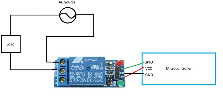
- Connect the Vcc to the Vcc of the Arduino (5v).
- Connect the GND to GND of the Arduino.
- Connect the input of the relay to any GPIO on the Arduino we in the next code we will use pin number 2.
The relay has three terminals - NO (Normally Open), NC (Normally Closed), and COM (Common).
- Load Connected to NO Terminal: In this setup, the electrical load (e.g., a light bulb or any other appliance) is connected to the NO terminal of the relay. The COM terminal has the live wire connected to it. When the relay is not activated (OFF state), the connection between COM and NC is established, and the load is not powered. However, when the relay is activated (ON state), the connection between COM and NO is established, and the load gets powered up and connected to the live wire.
- Load Connected to NC Terminal: In this configuration, the load is connected to the NC terminal of the relay, while the live wire is connected to the COM terminal. With this setup, the load remains powered and connected to the live wire by default, even when the relay is not activated (OFF state). But when the relay is activated (ON state), the connection between COM and NC breaks, disconnecting the load from the live wire and turning it off.
depending on whether the load is connected to the NO or NC terminal, the relay's activation will either power on the load (NO terminal setup) or power off the load (NC terminal setup).
Library:
This Module doesn't need a library to work.
Code:
This code controls a relay connected to pin 2 of the microcontroller. The relay is used to switch a high-current load (e.g., a motor, light, or any electrical appliance) and it will give the status of the relay on the serial monitor:
// Pin to control the relay
const int relayPin = 2;

void setup() {
  pinMode(relayPin, OUTPUT);
  digitalWrite(relayPin, HIGH); // Turn the relay off initially

  // Start serial communication with the computer
  Serial.begin(9600);
}

void loop() {
  digitalWrite(relayPin, LOW);  // Turn the relay ON by making the voltage LOW
  Serial.println("Relay Status: ON");
  delay(1000);                 // Wait for a second

  digitalWrite(relayPin, HIGH); // Turn the relay off (HIGH is the voltage level)
  Serial.println("Relay Status: OFF");
  delay(1000);                 // Wait for a second
}
- Pin and Serial Setup: The code defines a constant integer variable
relayPinand sets it to 2. This variable represents the pin number on the microcontroller to which the relay is connected. Thesetup()function is then executed, where it setsrelayPinas an output pin usingpinMode(relayPin, OUTPUT). Additionally, the initial state of the relay is set to OFF (HIGH state) usingdigitalWrite(relayPin, HIGH). - Serial Communication Setup: The code starts serial communication with the computer by calling
Serial.begin(9600). This allows communication between the microcontroller and a computer via the Serial Monitor. - Loop Function: The
loop()function is where the main functionality of the code resides. It runs continuously in an infinite loop. - Relay ON: Inside the
loop()function, the code turns ON the relay by setting the voltage onrelayPinto LOW usingdigitalWrite(relayPin, LOW). This action powers the relay coil, causing the relay to switch to the ON state, and the high-current load connected to the relay will be powered. Then, the code sends a message "Relay Status: ON" to the Serial Monitor usingSerial.println("Relay Status: ON"). After that, the code introduces a delay of 1000 milliseconds (1 second) usingdelay(1000). - Relay OFF: After the 1-second delay, the code turns OFF the relay by setting the voltage on
relayPinto HIGH usingdigitalWrite(relayPin, HIGH). This action de-energizes the relay coil, causing the relay to switch to the OFF state, and the high-current load connected to the relay will be disconnected. The code then sends a message "Relay Status: OFF" to the Serial Monitor usingSerial.println("Relay Status: OFF"). Another 1-second delay is introduced usingdelay(1000). - Loop Continuation: The loop continues, and the relay ON/OFF cycle repeats indefinitely.
Technical Details:
- 1 Channel
- Supply voltage – 3.3V to 5V
- Trigger current – 50mA - 60mA
- Quiescent current: 2mA
- Relay maximum contact voltage – 250VAC, 30VDC
- Relay maximum current – 10A
- 5. Size: approx. 41x16x16mm/1.61x0.62x0.62'
- 6. Weight: approx. 12g
Resources:
Comparisons:
comparison between relay modules with optocouplers to those without optocouplers, similar to the module (low trigger, power and status LEDs, 1 relay, screw terminal, 10A relay):
Relay Module with Optocoupler:
- Isolation: The main advantage of the relay module with an optocoupler is that it provides electrical isolation between the low-voltage control circuit and the high-current load. The optocoupler ensures that there is no direct electrical connection between the control circuit and the load side, reducing the risk of noise, voltage spikes, and potential damage to sensitive components.
- Safety: The inclusion of an optocoupler enhances safety in applications where electrical isolation is crucial. It protects the microcontroller or control circuit from high-voltage transients or faults that might occur on the load side.
- Interference: The optocoupler acts as a barrier to prevent interference or ground loops between the control circuit and the load. This can lead to improved reliability and stability in the control system.
- Price: Relay modules with optocouplers are generally slightly more expensive than those without optocouplers due to the additional components and features.
Relay Module without Optocoupler:
- No Isolation: The primary difference compared to the module with an optocoupler is that this relay module lacks electrical isolation between the control circuit and the high-current load. As a result, the control circuit and load side share a common ground, and potential interference or voltage fluctuations can impact the control system.
- Simplicity and Affordability: Relay modules without optocouplers are simpler in design, with fewer components, which makes them more cost-effective and affordable.
- Application Specific: These modules are suitable for applications where electrical isolation is not a concern, or where additional measures are taken to ensure proper grounding and noise immunity.
- Suitable for Non-Critical Applications: The relay modules without optocouplers are commonly used in less critical applications where the risk of interference or voltage spikes is minimal, and the cost is a significant consideration.
Comparison Summary:
- The presence of an optocoupler is the key distinguishing feature between the two types of relay modules.
- Relay modules with optocouplers provide electrical isolation, enhanced safety, and better noise immunity, making them suitable for applications where these factors are critical.
- Relay modules without optocouplers are more straightforward and cost-effective, making them suitable for non-critical applications or projects with budget constraints.
- Choosing between the two depends on the specific requirements of the application. For safety-critical or noise-sensitive projects, the module with an optocoupler is recommended. For simpler, budget-friendly projects, the module without an optocoupler can be a suitable choice, provided proper precautions are taken for grounding and interference mitigation.