AED 19.95
Description
This is a remote control kit with a decoding receiver board that operates at a frequency of 315 MHz and a voltage of 5V. The board uses super regeneration technology and the ASK modulation method. It has an encoding chip SC2272 that is compatible with PT2272 and PT2294 chips. The remote control operates at a voltage of 12V and has four buttons that correspond to the four data bits of the board's output pins. The remote uses the ASK modulation method and has a transmission frequency of 315Mhz with a transmission distance of 50-100m in an open field. It uses a fixed code encoder. The kit can be used to control relays, such as those used for garage doors.
Package Includes:
- 1 x Wireless Remote Control and Receiver Module 315MHz 4 channel 4 Key Kit
Features:
Remote control:
- Allows remote control of a relay, such as for opening and closing a garage door
- Four buttons on the remote control corresponding to the four data bits of the decoding receiver board's output pins
- Uses ASK modulation method to transmit signals
- Fixed code encoder for signal encoding
Decoding receiver board:
- Can be used to remotely control a relay, such as for opening and closing a garage door
- Operates at a frequency of 315Mhz
- Requires a DC voltage of 5V to operate
- Uses super regeneration technology for high sensitivity and selectivity
- Uses ASK modulation method for digital signal transmission
- Compatible with SC2272, PT2272, and PT2294 encoding chips
- Has better than -105dBm sensitivity (50Ω)
- Output signal: non-lock (M)
- The low operating current of ≤3mA at 5VDC
- Can be used with any device or appliance that requires relay control
Description:
This is an RF Kit remote control and decoding receiver board that can be used to remotely control a relay, such as for opening and closing a garage door. The kit consists of two main components: the remote control and the decoding receiver board. The decoding receiver board operates at a frequency of 315Mhz and requires a DC voltage of 5V to operate. It has a low operating current of ≤3mA at 5VDC, making it energy-efficient. The board uses super regeneration technology, which is a method of amplification and detection of radio frequency signals that provide high sensitivity and selectivity. Additionally, it uses the amplitude-shift keying (ASK) modulation method, which is a digital modulation technique that uses variations in the amplitude of a carrier wave to represent digital information.
Principle of Work:
The RF Kit remote control and decoding receiver board work together to allow remote control of a relay, such as for opening and closing a garage door. When a button is pressed on the remote control, it sends a signal to the decoding receiver board using the ASK modulation method. The signal is transmitted at a frequency of 315Mhz and is encoded using a fixed code encoder. The signal is picked up by the decoding receiver board, which has a sensitivity of better than -105dBm, meaning it can detect signals from a distance without much interference. The decoding receiver board uses the SC2272 encoding chip to decode the incoming signal and convert it into output signals that correspond to the four data bits of the board's output pins (D0, D1, D2, and D3). When a button is pressed on the remote control, a signal is sent that causes the corresponding data bit output to become HIGH. The decoding receiver board then uses the output signals to control a relay, such as for opening and closing a garage door. The relay is connected to the board's output pins, and when the board's output pins become HIGH, the relay is activated, allowing it to switch on or off a device or appliance.
Pinout of the Module:
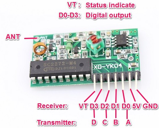
- Pin 1: VCC (+5V) - This pin is used to supply power to the decoding receiver board.
- Pin 2: GND - This pin is the ground for the board and should be connected to the negative terminal of the power supply.
- Pin 3: D0 - This pin outputs the decoded signal corresponding to the first button of the remote control.
- Pin 4: D1 - This pin outputs the decoded signal corresponding to the second button of the remote control.
- Pin 5: D2 - This pin outputs the decoded signal corresponding to the third button of the remote control.
- Pin 6: D3 - This pin outputs the decoded signal corresponding to the fourth button of the remote control.
- Pin 7: VT - This is a valid transmission indicator output pin. When a valid signal is received, this pin will go high.
- Pin 8: ANT- This pin is used for connecting Antenna.
Applications:
- Garage door control - The kit can be used to remotely open and close a garage door.
- Lighting control - The kit can be used to remotely control lighting, such as turning on and off a set of lights.
- Security systems - The kit can be used to remotely arm and disarm security systems.
- Industrial automation - The kit can be used to remotely control industrial equipment and machinery.
- Remote control for toys - The kit can be used to remotely control toys, such as remote-controlled cars.
- Home automation - The kit can be integrated with a home automation system to remotely control appliances, such as turning on the coffee maker in the morning.
- Wireless communication - The kit can be used to establish a wireless communication link between two devices or systems.
Circuit:
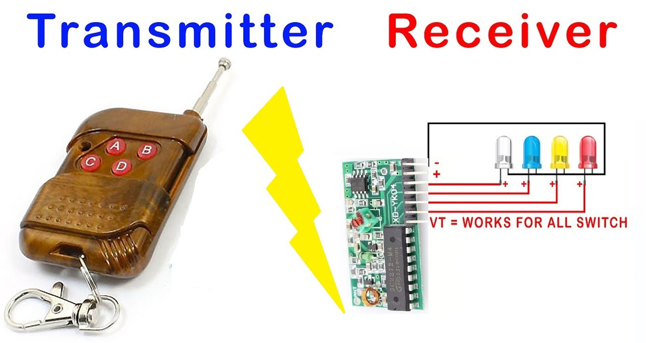
Here is how to connect four LEDs to the decoding receiver board of the RF Kit remote control and how to control them using the kit:
- Connect power and ground to the decoding receiver board. Connect the VCC pin (pin 1) of the decoding receiver board to a 5V power supply and the GND pin (pin 2) to the ground of the power supply.
- Connect the output pins of the decoding receiver board to the LEDs. Connect each of the D0-D3 output pins (pins 3-6) of the decoding receiver board to a separate LED through a current-limiting resistor. The value of the resistor will depend on the LED and power supply voltage used, but a value of around 220 ohms should work in most cases.
- Test the LED connections. Turn on the power supply and test each of the LEDs to make sure they light up when the corresponding button on the remote control is pressed.
- Optional: Add a transistor for higher current loads. If you want to control higher current loads than the LEDs can handle directly, you can connect a transistor to each output pin of the decoding receiver board and use the transistor to switch the higher current load.
- Control the LEDs using the remote control. Press the corresponding button on the remote control to turn on and off each of the LEDs connected to the decoding receiver board.
Library:
no library is needed.
Code:
no code is needed for this kit to work.
Technical Details:
-
The Decoding receiver board:- Working frequency: 315M- Operating voltage: DC5V- Operating current: ≤3mA(5.0VDC)- Working principle: super regeneration- Modulation method: ASK- Encoding chip: SC2272 (PT2272, PT2294), chip compatible- Sensitivity: better than -105dBm (50Ω)- Output signal: non-lock (M)
-
Remote control:Operating voltage: DC12V (27A/12V battery x1)Operating Current: 10mA @ 12V
Radiated power: 10mw @ 12V
Size: 6.2 x 3.8 x1.4cm(LxWxD)
Modulation mode: ASK (Amplitude Modulation)
Transmitting frequency: 315MHZ (SAW frequency stabilization)
Transmission distance:50-100M (Open field the receiver sensitivity -100dbm)
Encoder types: fixed code
Resources:
Comparisons:
The difference between the Wireless Remote Control and Receiver Module 315MHz 4 channel 4 Key Kit and the Wireless Remote Control and Receiver Module 433MHz 4 channel 4 Key Kit is the operating frequency.
The 315MHz kit operates at a lower frequency than the 433MHz kit. This can affect the range of the wireless signal and the ability to penetrate through walls and other obstacles. Generally, lower frequencies have better ranges and are less affected by obstacles than higher frequencies, but they can be more susceptible to interference from other devices operating at similar frequencies. In terms of functionality, both kits are very similar. They each consist of a wireless remote control and a receiver module with four channels and four keys. The receiver modules can be used to control a variety of devices, such as relays or LEDs, depending on the specific application.
The choice between the 315MHz and 433MHz kits will depend on the specific requirements of the application. If long-range performance is critical, the 315MHz kit may be a better choice.