AED 42.50
Description
The Arduino Micro Pro is similar to the Leonardo, but it is smaller and has a bit more functionality, the MCU "ATmega32U4" serves as the board's core. it has an embedded USB interface. Users can configure work as a keyboard or a mouse when connected to a PC.
Package Includes:
- 1 x Arduino Pro Micro 5V/16Mhz (Compatible)
Features:
-
Microcontroller:- ATmega32U4
-
Operating Voltage:- 5
-
Input Voltage:- 5 - 12 V ( If use 5V, input 5V to Vcc, if used above 5V, input to RAW pin)
-
micro USB connection
-
9x10-bit Analog input pins
-
18 x digital I/O pins
-
5 x PWM pins
-
RX/TX serial port
- Flash Memory: 32KB
- SRAM: 2.5KB
-
Clock Speed 16MHz
-
5v regulating circuit
- Pin 13 LED no
Description:
The Arduino Micro Pro is similar to the Leonardo, but it is smaller and has a bit more functionality, the MCU "ATmega32U4" serves as the board's core. it has an embedded USB interface. Users can configure work as a keyboard or a mouse when connected to a PC. It has a frequency of 16MHz and a voltage of 5V. It has four analog 9 pins, 18 digital I/O pins, and 5 PWM pins. Furthermore, it supports serial communication UART via pins Rx and Tx. Arduino. cc provides an open-source platform that allows for hardware and software customization.
Principle of Work:
In 2005, Arduino boards were introduced in Italy with the goal of providing a single platform where non-technologists could obtain these boards and develop electronic devices that could interact with the environment using actuators and sensors. These boards are so simple to use that even the most inexperienced user can operate them. Arduino is Free hardware which is anything whose blueprints and specs are available for anybody to copy. This means that Arduino provides the framework so that any other individual or business can design their own boards, each of which can be unique yet function well when built upon the same framework. Free software is a computer program whose source code is available to anybody, allowing them to use and alter it as they see fit. In order to allow anyone to create apps for Arduino boards and provide them with a variety of utilities, Pro Micro works with the Arduino IDE (Integrated Development Environment) platform. which you can use to program and upload your code (sketch) and do this using a Built-in USB Functionality without the need for any external programmer just write your code on Arduino IDE then press the upload button and the code will be on your board ready to be used.
Pinout of the Module:
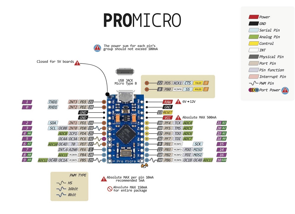
Digital I/O Pins: The board has 18 digital I/O pins that can be used as input or output depending on the application. These pins are either turned off or turned on. When they are turned on, they receive 5V and are classified as HIGH; when they are turned off, they receive 0V and are classified as LOW.
Analog Pins: This board has 9 channels of 10-bit ADC. These are analog pins that can receive any number of values, as opposed to digital pins which can only receive two values, HIGH and LOW.
PWM Pins: The Pro Micro board includes 5 PWM channels for obtaining some of the analog output's functions. When the PWM pins are activated, the board generates analog output using digital means.
UART Pins: It gives UART serial communication via two pins, Rx and Tx. Both pins are used for serial data transmission and receiving.
SPI Pins: This board includes a serial peripheral interface (SPI), which is used to establish communication between the MCU and other devices such as sensor-shift registers. SPI communication uses two pins: MOSI (Master Output Slave Input) and MISO (Master Input Slave Output) - these pins are used by the microcontroller to send and receive data.
I2C Pins:
- Two pins are used for I2C communication which is a two-wire communication protocol. One is SDA and the other is SCL.
- The former is a serial data line used to carry the data and the latter is a serial clock line used for the synchronization of all data transfer over the I2C bus.
Power Pins
There are a variety of power and power-related nets broken out:
- RAW: is the Pro Micro's unregulated voltage input. When powered by USB, the voltage at this pin will be around 4.8V (USB's 5V minus a Schottky diode drop). If the board is powered from outside, the applied voltage can be as high as 12V.
- VCC: is the voltage supplied to the onboard ATmega32U4. is 5V this voltage is regulated by the voltage applied to the RAW pin. If the board is powered through the 'RAW' pin (or USB), this pin can be used as an output to supply other devices.
- RST: can be used to restart the Pro Micro. This pin is pulled high by a 10kOhm, resistor on the board, and is active-low, so it must be connected to the ground to initiate a reset. The Pro Micro will remain "off" until the reset line is pulled back to high.
- GND: is the common, ground voltage (0V reference) for the system.
Applications:
- IoT Systems.
- Embedded systems.
- Work as a keyboard or a mouse.
- Windows PC lock/unlock application
- USB Trackpad
- USB Joystick
- Water Level Meter
- Electric Bike
- Creating a wireless keyboard
- Automatic Pill Dispenser
Circuit:
We will not need any circuit, in this testing code, we will print out byte values in all possible formats on the serial monitor.
Connecting with Arduino First Time
1. Open Arduino IDE
If you haven’t done so already, download Arduino IDE from the software page.
You don't need to install any drivers.
2. Connect the board to your computer:
connect the board to your computer with a USB cable. This will both power the board and allow the IDE to send instructions to the board. You’ll need a data USB cable (a charge-only cable will not work), with connectors that fit both the board and your computer.
3. Select Board:
you need to tell Arduino IDE which board your sketch is for.
Click on Tools in the menu bar and find the Board row. If a board is currently selected it will be displayed here.
The tools menu with the Board row is highlighted.
Hover over the Board row to reveal the installed board packages.
Click on the Arduino Micro or (Leonardo) board to select it.
Selecting a board in Arduino IDE.
4. Select port: Click on Tools in the menu bar and find the Port row. If a board is currently selected it will be displayed here.
The tools menu with the Port row highlighted.
Select the serial device of the Arduino board from the Tools | Serial Port menu. This is likely to be COM3 or higher (COM1 and COM2 are usually reserved for hardware serial ports). To find out, you can disconnect your Arduino board and re-open the menu; the entry that disappears should be the Arduino board. Reconnect the board and select that serial port.
5. Upload a sketch
Copy the code below.
Optional: Click the Verify button to try compiling the sketch and check for errors.
Click the Upload button to program the board with the sketch.
Your sketch will start running on the board. It will run again each time the board is reset.
Now you can open the Serial Monitor by clicking on the icon in the upper right corner.
Code:
void setup() {
  //Initialize serial and wait for port to open:
  Serial.begin(9600);
  while (!Serial) {
    ; // wait for serial port to connect. Needed for native USB port only
  }

  // prints title with ending line break
  Serial.println("ASCII Table ~ Character Map");
}

// first visible ASCIIcharacter '!' is number 33:
int thisByte = 33;
// you can also write ASCII characters in single quotes.
// for example, '!' is the same as 33, so you could also use this:
// int thisByte = '!';

void loop() {
  // prints value unaltered, i.e. the raw binary version of the byte.
  // The Serial Monitor interprets all bytes as ASCII, so 33, the first number,
  // will show up as '!'
  Serial.write(thisByte);

  Serial.print(", dec: ");
  // prints value as string as an ASCII-encoded decimal (base 10).
  // Decimal is the default format for Serial.print() and Serial.println(),
  // so no modifier is needed:
  Serial.print(thisByte);
  // But you can declare the modifier for decimal if you want to.
  // this also works if you uncomment it:

  // Serial.print(thisByte, DEC);


  Serial.print(", hex: ");
  // prints value as string in hexadecimal (base 16):
  Serial.print(thisByte, HEX);

  Serial.print(", oct: ");
  // prints value as string in octal (base 8);
  Serial.print(thisByte, OCT);

  Serial.print(", bin: ");
  // prints value as string in binary (base 2) also prints ending line break:
  Serial.println(thisByte, BIN);

  // if printed last visible character '~' or 126, stop:
  if (thisByte == 126) {    // you could also use if (thisByte == '~') {
    // This loop loops forever and does nothing
    while (true) {
      continue;
    }
  }
  // go on to the next character
  thisByte++;
}
Technical Details:
- CPU 8bit
- Microcontroller Atmega32u4
- Operating voltage 5V
- Input voltage max. 12V
- Weight: ~ 6 grams
- Dimension: 3.4cm x 1.8cm
Resources:
- You might also want to look at: the reference for the Arduino language.
- Getting Started Tutorial
- The Sparkfun Version Tutorial
Comparisons:
This board differs slightly from the Arduino Micro and Leonardo boards. The Arduino Pro Micro lacks a reset button, a 13-pin LED, and an ICSP header, and it is smaller in size than the Arduino Micro board. It also lacks pins such as AREF, A4, A5, SS, 11, 12, and 13. This also implies that while pin 13 does not carry an LED, it does support Tx and Rx pins with LEDs for serial communication. and this board differs from the UNO board which it doesn't include any serial converter so because the MCU has a built-in USB interface, on the other hand, the starting of the Serial Connection takes a little bit more time when the board reset that's why you see a delay() after every serial begin in the micro and Leonardo boards codes.