AED 25.00
Description
The DRV8825 stepper motor driver with heat sink is a high-performance device designed for precise motion control in automated systems. It offers versatile control options, including speed, direction, and torque, making it ideal for a wide range of applications, including CNC machines, 3D printers, and other precision-based systems. The built-in heat sink helps to dissipate heat generated during operation, preventing thermal overload and ensuring stable and reliable performance. With its compact design and ease of use, the DRV8825 is a reliable and efficient solution for any project requiring precise motion control.
Package Includes:
- 1 x DRV8825 Stepper Motor Driver With Heat Sink
Features:
- The DRV8825 stepper motor driver with heat sink provides precise motion control for automated systems
- Operating voltage range of 8.2V to 45V, with a maximum current per phase of 2.5A, making it suitable for a wide range of applications
- Microstep resolution options (full step, 1/2 step, 1/4 step, 1/8 step, 1/16 step, and 1/32 step) for precise control of the connected stepper motor
- Built-in safety features including over-temperature shutdown, under-voltage lockout, and over-current shutdown to protect the system
- Short-to-ground and shorted-load protection and low RDS(ON) outputs for improved efficiency
- The compact size of 20.5 x 15.5 mm (0.8" x 0.6") for convenient integration into various systems and projects.
Description:
The DRV8825 stepper motor driver with heat sink is a compact and reliable solution for precise motion control in automated systems. It can operate between 8.2V and 45V and provides a maximum current per phase of 2.5A, making it suitable for a wide range of applications. With its micro step resolution options, including full step, 1/2 step, 1/4 step, 1/8 step, 1/16 step, and 1/32 step, it offers precise control for precise motion control. This driver also features over-temperature shutdown, under-voltage lockout, and over-current shutdown for added protection. Additionally, it has short-to-ground and shorted-load protection, as well as low RDS(ON) outputs for improved efficiency. With dimensions of 20.5 x 15.5 mm, the DRV8825 is a compact and convenient option for precise motion control projects.
Principle of Work:
Stepper motors are commonly used in applications where precise control of position or speed is required, such as in 3D printers, CNC machines, or robotics. The DRV8825 stepper motor driver with heat sink is specifically designed to provide an easy and convenient solution for controlling the motion of a stepper motor. The driver receives input control signals from a microcontroller or other control device and converts them into the electrical current needed to drive the stepper motor. The micro-step resolution options allow for precise control of the motor's rotation, with smaller steps providing more precise control.
The built-in safety features of the DRV8825 include over-temperature shutdown, under-voltage lockout, and over-current shutdown. These features protect both the driver and the connected stepper motor from damage in the event of an over-temperature, under-voltage, or over-current condition. The short-to-ground and shorted-load protection of the DRV8825 help to prevent damage to the driver or the connected motor in the event of a short circuit. The low RDS(ON) outputs of the driver help to minimize power loss, improving its overall efficiency.
The compact size of the DRV8825 makes it an ideal solution for use in tight spaces, and its heat sink helps to ensure its stable operation even in high-temperature environments. With its precise motion control capabilities and built-in safety features, the DRV8825 stepper motor driver with heat sink is a reliable and convenient option for a wide range of precise motion control applications.
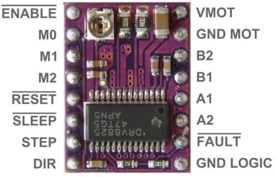
Pinout of the Module:
-
STEP: This is the step input pin. It is used to provide step pulses to the driver, which determines the speed and direction of the motor's rotation. The step input pin should be connected to a control device, such as a microcontroller or a driver controller board, which generates the step pulses.
-
DIR: The direction input pin is used to set the direction of rotation of the motor. The pin should be connected to a control device that provides a digital signal to indicate the desired direction of rotation.
-
MS1, MS2, MS3: These pins are used to select the micro-step resolution of the driver. By connecting different combinations of these pins to either Vcc or GND, the driver can be configured for full step, half step, quarter step, and so on, up to 1/32 step resolution. These pins should be connected to a control device that provides the necessary signals to select the desired micro step resolution.
-
EN: The enable input pin is used to enable or disable the driver. When the enable pin is high, the driver is enabled, and the motor will rotate in response to step pulses. When the enable pin is low, the driver is disabled, and the motor will not move. This pin should be connected to a control device that provides the necessary signals to enable and disable the driver.
-
Vcc: This is the power supply input pin. The DRV8825 requires a regulated DC power supply of between 8.2V and 45V, and this pin should be connected to the positive voltage source.
-
GND: The ground pin should be connected to a common ground with the control device and the power supply. This provides a reference voltage for the driver and helps to reduce electrical noise and interference.
-
A+, A-: These are the output pins for phase A of the stepper motor. They should be connected to the corresponding phase wires of the motor. The driver uses these output pins to generate the current needed to drive phase A of the motor.
-
B+, B-: These are the output pins for phase B of the stepper motor. They should be connected to the corresponding phase wires of the motor. The driver uses these output pins to generate the current needed to drive phase B of the motor.
| Microstep Resolution | Combination | M0, M1, M2 Combination |
|---|---|---|
| Full Step | 1.00 | Low, Low, Low |
| 1/2 Step | 0.50 | High, Low, Low |
| 1/4 Step | 0.25 | Low, High, Low |
| 1/8 Step | 0.125 | High, High, Low |
| 1/16 Step | 0.0625 | Low, Low, High |
| 1/32 Step | 0.03125 | High, High, High |
Applications:
The DRV8825 stepper motor driver with heat sink can be used in a variety of applications that require precise motion control, including:
- CNC machines
- Robotics
- 3D printers
- Printing machines
- Medical equipment
- Elevators
- Automated conveyor systems
- Textile machines
- Engraving machines
These applications typically involve situations where a precise and controlled rotational motion is required, and the DRV8825 provides a reliable solution for achieving this level of precision and control.
Circuit:
connect the DRV8825 Stepper Motor driver to Arduino and control NEMA17 Stepper Motor. We used D2 & D3 pins to control the motor direction and step
A 12V power supply powers the VMOT pin, whereas a 5V supply powers the VDD pin. Never forget to cross the motor power supply pins with a sizable 100 F decoupling electrolytic capacitor that is located close to the board.

Library:
no need to install Library to work with this item.
Code:
This code is an example of how to control a stepper motor using an Arduino board.
const int dirPin = 2;
const int stepPin = 3;
const int stepsPerRevolution = 200;
void setup()
{
 // Declare pins as Outputs
 pinMode(stepPin, OUTPUT);
 pinMode(dirPin, OUTPUT);
}
void loop()
{
 // Set motor direction clockwise
 digitalWrite(dirPin, HIGH);
 // Spin motor slowly
 for(int x = 0; x < stepsPerRevolution; x++)
 {
 digitalWrite(stepPin, HIGH);
 delayMicroseconds(2000);
 digitalWrite(stepPin, LOW);
 delayMicroseconds(2000);
 }
 delay(1000); // Wait a second
 // Set motor direction counterclockwise
 digitalWrite(dirPin, LOW);
 // Spin motor quickly
 for(int x = 0; x < stepsPerRevolution; x++)
 {
 digitalWrite(stepPin, HIGH);
 delayMicroseconds(1000);
 digitalWrite(stepPin, LOW);
 delayMicroseconds(1000);
 }
 delay(1000); // Wait a second
}
- The first two lines define the pins connected to the stepper motor's direction and step inputs as constants.
- In the
setup()function, the pins are declared as outputs using thepinMode()function. - In the
loop()function, the motor direction is set to clockwise using, and the motor is then made to rotate slowly by iterating a loop that generates step pulses at a rate of 2000 microseconds delay per pulse. The direction is then set counterclockwise usingdigitalWrite(dirPin, LOW)and the motor is made to rotate quickly by iterating another loop with a 1000 microseconds delay per pulse. - After each loop execution, a delay of 1 second is introduced using
delay(1000)to allow the motor to stabilize before changing direction and speed again.
Technical Details:
- Detection range of 2 - 20cm
- Detection angle of 35º
- It can be used for 3-5V power supply modules. When wired directly, the red indicator light will be on.
- The output port can be directly linked to the IO port of the project's microcontroller. A 5V relay can easily be connected
- to pins (VCC, VCC, GND, GND, OUT, and IO)
- Board size - 3.1 x 1.5cm
- Pins on the module board - VCC (external 3.3 - 5V, which can be easily wired to either 3.3V or 5V MCU); GND external; and out for small board digital output interfaces (0 and 1)
- The distance that the module can detect within the specified range can be adjusted through the use of a potentiometer
Resources:
Comparisons:
The DRV8825 and A4988 are both stepper motor drivers that are used to control the motion of a stepper motor. However, there are some differences between the two:
-
Microstepping: The DRV8825 supports a higher level of micro-stepping (1/32) compared to the A4988 (1/16). Microstepping allows for smoother control of the motor's motion.
-
Voltage: The DRV8825 can operate with a wider input voltage range (8.2 - 45 V) compared to the A4988 (8 - 35 V).
-
Overcurrent protection: The DRV8825 has an internal thermal shutdown and over-current protection, whereas the A4988 relies on external circuitry for thermal protection.
-
Heatsinking: The DRV8825 has a larger thermal pad for better heat dissipation compared to the A4988.
-
Power Dissipation: The DRV8825 can handle a higher current per phase (2.5A) compared to the A4988 (2A). However, this also means the DRV8825 may dissipate more heat than the A4988.
In conclusion, the DRV8825 is a more advanced and feature-rich stepper motor driver compared to the A4988, but it may also be more expensive and require better heatsinking. The choice between the two ultimately depends on the specific requirements of the application.