AED 35.00
Description
The PCA9685 16-Channel Servo Driver, which uses an onboard PWM controller to drive all 16 channels at the same time, is used to connect multiple servo motors over I2C. You can also connect multiple PCA9685 16-Channel Servo Drivers in a chain of up to 62 drivers. As a result, the two I2C pins can control up to 992 servos
Package Includes:
- 1 x Servo Motor PWM Driver I2C Module 16-channel 12-bit PCA9685
Features:
- Can control up to 16 servo motors simultaneously
- Uses a single I2C interface for communication with a microcontroller or other control device
- The onboard PWM controller generates pulse width modulated (PWM) signals for all 16 channels
- Can be connected in a chain with up to 62 other PCA9685 drivers, allowing for control of up to 992 servo motors using just two I2C pins
- Can operate at a wide range of voltages (3.3V to 5V)
Description:
The PCA9685 16-Channel Servo Driver is a device that allows you to control multiple servo motors using a single I2C interface. It uses an onboard PWM controller to generate the pulse width modulated (PWM) signals required to drive the servo motors and can control up to 16 servos at the same time. One of the benefits of using the PCA9685 16-Channel Servo Driver is that it allows you to control a large number of servos using a single I2C interface, which can save on the number of pins required on your microcontroller or another control device. Additionally, you can connect multiple PCA9685 drivers in a chain, allowing you to control up to 992 servos using just two I2C pins.
Principle of Work:
The PCA9685 16-Channel Servo Driver is a device that allows you to control multiple servo motors using a single I2C interface. It works by generating pulse width modulated (PWM) signals that are sent to the servo motors to control their position and other characteristics.
The PCA9685 16-Channel Servo Driver board has an onboard PWM controller that is responsible for generating the PWM signals. These signals are generated based on the values that are sent to the board over the I2C interface from a microcontroller or other control device. The PWM controller on the board is able to generate PWM signals for all 16 channels simultaneously, allowing you to control multiple servo motors at the same time.
To use the PCA9685 16-Channel Servo Driver, you will need to connect it to your microcontroller or other control device using the I2C interface, and then connect the servo motors to the appropriate channels on the driver. You will also need to provide a power source for the servo motors and the driver, and ensure that the voltage and current requirements of the servos are met.
Once the PCA9685 16-Channel Servo Driver is properly connected and configured, you can use it to control the position, speed, and other characteristics of the servo motors using your control device and appropriate software or firmware.
Pinout of the Motor:
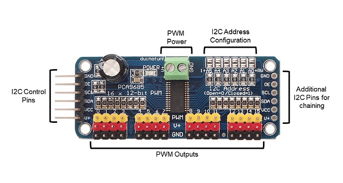
The PCA9685 16-Channel Servo Driver board has the following pins:
- VCC: This is the power pin, which should be connected to the operating voltage of the board (3.3V to 5V).
- GND: This is the ground pin, which should be connected to the ground of the circuit.
- SDA: This is the serial data pin for the I2C interface, which should be connected to the SDA pin on your microcontroller or another control device.
- SCL: This is the serial clock pin for the I2C interface, which should be connected to the SCL pin on your microcontroller or another control device.
- OE: This is the output enable pin, which can be used to enable or disable the output of the PWM signals from the board.
- SLEEP: This is the sleep mode pin, which can be used to put the board into a low-power sleep mode.
- RESET: This is the reset pin, which can be used to reset the board.
In addition to these pins, the PCA9685 16-Channel Servo Driver board has 16 output channels, each of which can be used to connect a servo motor. The output channels are labeled 0 through 15, and each one includes an output terminal for the PWM signal and a ground terminal. To use a servo motor with the board, you will need to connect the signal wire of the servo to the appropriate output terminal and the ground wire to the corresponding ground terminal.
Applications:
The PCA9685 16-Channel Servo Driver board is primarily used to control servo motors in a variety of applications. Some common examples include:
-
Robotics: The PCA9685 16-Channel Servo Driver board can be used to control the movement of robotic arms, legs, or other manipulators. It can also be used to actuate other mechanisms or devices in a robot, such as doors or levers.
-
Model building: The PCA9685 16-Channel Servo Driver board can be used to control the movement of servo motors in model airplanes, cars, boats, and other types of models.
-
Automation: The PCA9685 16-Channel Servo Driver board can be used to control the movement of servo motors in automated systems, such as conveyor belts or other types of machinery.
-
Other DIY projects: The PCA9685 16-Channel Servo Driver board can be used in a wide range of other DIY electronics projects, such as control systems for small fans or pumps, or to actuate other types of mechanisms or devices.
Circuit:
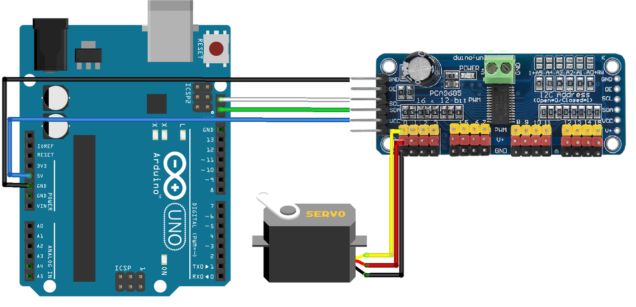
The module includes an I2C bus and a power input. The I2C bus is linked in the following way:
Pin A5 or SCL to the module's SCL pin
Pin A4 or SDA to the module's SDA pin
Connect pin 5V to the module's Vcc pin.
Connect GND to the module's GND pin. We use the Arduino UNO board, but it may be extended to different microcontrollers.
Library:
You need to download and add the next library to Arduino IDE
Code:
//Libraries
#include "Wire.h"
#include "Adafruit_PWMServoDriver.h"
//Constants
#define nbPCAServo 16
//Parameters
int MIN_IMP [nbPCAServo] ={500, 500, 500, 500, 500, 500, 500, 500, 500, 500, 500, 500, 500, 500, 500, 500};
int MAX_IMP [nbPCAServo] ={2500, 2500, 2500, 2500, 2500, 2500, 2500, 2500, 2500, 2500, 2500, 2500, 2500, 2500, 2500, 2500};
int MIN_ANG [nbPCAServo] ={0, 0, 0, 0, 0, 0, 0, 0, 0, 0, 0, 0, 0, 0, 0, 0};
int MAX_ANG [nbPCAServo] ={180, 180, 180, 180, 180, 180, 180, 180, 180, 180, 180, 180, 180, 180, 180, 180};
//Objects
Adafruit_PWMServoDriver pca= Adafruit_PWMServoDriver(0x40);
void setup(){
//Init Serial USB
Serial.begin(9600);
Serial.println(F("Initialize System"));
pca.begin();
pca.setPWMFreq(60);  // Analog servos run at ~60 Hz updates
}
void loop(){
  pcaScenario();
}
void pcaScenario(){/* function pcaScenario */
////Scenario to test servomotors controlled by PCA9685 I2C Module
for (int i=0; iMIN_IMP[i];pos-=10){
        pca.writeMicroseconds(i,pos);delay(10);
      }
      for(int pos=MIN_IMP[i];pos<(MAX_IMP[i]+MIN_IMP[i])/2;pos+=10){
        pca.writeMicroseconds(i,pos);delay(10);
      }
      pca.setPin(i,0,true); // deactivate pin i
    }
}
int jointToImp(double x,int i){/* function jointToImp */
////Convert joint angle into pwm command value
      int imp=(x - MIN_ANG[i]) * (MAX_IMP[i]-MIN_IMP[i]) / (MAX_ANG[i]-MIN_ANG[i]) + MIN_IMP[i];
      imp=max(imp,MIN_IMP[i]);
      imp=min(imp,MAX_IMP[i]);
 return imp;
}
Technical Details:
- Operating voltage: 3.3V to 5V
- Current consumption: up to 1.2A per channel, with a maximum of 3.2A for all channels combined
- PWM frequency: up to 1.6 kHz
- I2C address: configurable from 0x40 to 0x7F
- Operating temperature: -40°C to 85°C
- Control pulse width range: 150 µs to 600 µs
- Duty cycle resolution: 12-bit (0.24% resolution)
- Output rise time: 5 µs
- Output fall time: 5 µs
- Output enable time: 100 ns
- Output disable time: 100 ns
Resources:
Comparisons:
Controlling servo motors with an Arduino board and a PCA9685 16-Channel Servo Driver board is similar to controlling servo motors using an Arduino board alone, but there are a few key differences:
-
The number of servos: The PCA9685 16-Channel Servo Driver board allows you to control up to 16 servo motors simultaneously using a single I2C interface, while an Arduino board alone can typically control only a few servo motors at a time, depending on the number of available PWM outputs and the specific model of the Arduino board.
-
PWM frequency: The PCA9685 16-Channel Servo Driver board has an onboard PWM controller that can generate PWM signals with a frequency of up to 1.6 kHz, while the PWM frequency of an Arduino board alone is typically limited to around 500 Hz.
-
Accuracy and resolution: The PCA9685 16-Channel Servo Driver board has a 12-bit resolution for the duty cycle of the PWM signals, which allows for more precise control of the servo motors. An Arduino board alone typically has a resolution of 8 bits for PWM signals, which may be less precise.
Overall, using a PCA9685 16-Channel Servo Driver board can provide a more flexible and precise way to control servo motors in a project, but it does require an additional component and I2C interface. Whether or not it is the best choice will depend on the specific requirements of your project.