AED 95.00
Description
The Micro is an exceptional MCU development board crafted in collaboration with Adafruit, designed to unlock limitless possibilities. Powered by the advanced ATmega32U4, this board redefines innovation and empowers creators like never before. Equipped with 20 versatile digital I/O pins, including seven PWM outputs and twelve analog inputs, the Micro offers unparalleled flexibility for your projects. With a blazing Clock Speed of 16MHz, it ensures lightning-fast execution, enabling you to bring your ideas to life with remarkable speed and precision.
Package Includes:
- 1 x Arduino Micro Genuine
Features:
- ATmega32U4 MCU: Powered by the advanced ATmega32U4 microcontroller unit, offering high-performance capabilities and reliability.
- 20 Digital I/O Pins: Provides 20 flexible digital I/O pins, allowing you to interface with a wide range of external components and devices.
- PWM Outputs: Includes seven Pulse Width Modulation (PWM) outputs, enabling precise control over various actuators, motors, and other analog components.
- Analog Inputs: Offers twelve analog input channels, facilitating accurate sensing and measurement of real-world signals.
- 16MHz Clock Speed: Operates at a swift clock speed of 16MHz, ensuring rapid execution of instructions and efficient processing of data.
- Micro USB Connection: Features a micro USB interface for seamless connectivity with your computer, enabling easy programming and data transfer.
- Reset Button: Incorporates a convenient reset button for quick device rebooting or restarting during development and testing.
- User-Friendly Design: Designed with user convenience in mind, ensuring ease of use, setup, and integration with other hardware and software components.
- Extensive Documentation: Backed by comprehensive documentation and support from both Adafruit and the wider community, providing valuable resources for beginners and advanced users alike.
- Versatile Applications: Ideal for a wide range of projects, including robotics, Internet of Things (IoT) devices, automation systems, sensor interfacing, and prototyping.
Description:
The Arduino Micro is a compact yet powerful MCU development board, designed to ignite your creativity and take your projects to new heights. Building upon the success of the Leonardo, the Micro packs even more functionality into its smaller form factor, delivering a world of possibilities right at your fingertips. Created in collaboration with Adafruit, this exceptional board is based on the ATmega32U4 microcontroller, renowned for its reliability and performance. With a generous array of 20 digital I/O pins, the Micro offers unparalleled versatility. Among these pins are seven dedicated Pulse Width Modulation (PWM) outputs, granting you precise control over various actuators, motors, and analog components. Additionally, twelve analog inputs enable accurate sensing and measurement of real-world signals, expanding the range of applications you can explore. Seamless connectivity is at the core of the Micro's design. Featuring a micro USB connection, effortlessly establish a link between the board and your computer. But here's where the Micro truly shines: with its built-in USB functionality, it can be configured to act as a keyboard or a mouse when connected to a PC. This opens up exciting possibilities for human-computer interaction and enables seamless integration with existing software applications. Running at a frequency of 16MHz and powered by a 5V voltage supply, the Micro ensures rapid execution of instructions, allowing your projects to operate with speed and efficiency. Embracing the ethos of Arduino.cc, this development board provides an open-source platform that empowers you to customize both the hardware and software aspects of your projects. Tap into the vibrant Arduino community, where knowledge sharing and innovation thrive.
Unleash your creativity with the Arduino Micro. Whether you're embarking on your first electronics project or an experienced maker pushing the boundaries, this feature-rich board delivers the tools you need to bring your ideas to life. From robotics to interactive installations, IoT devices to custom input devices, the possibilities are limitless.
Principle of Work:
The Arduino Micro Genuine is designed to be an accessible and user-friendly development board for both beginners and experienced makers. and this is how the Arduino Micro Genuine works:
- Microcontroller: The heart of the Arduino Micro Genuine is the ATmega32U4 microcontroller, which is responsible for executing the code and controlling the board's functionalities.
- Programming: To program the Arduino Micro Genuine, you connect it to your computer using a micro USB cable. The board utilizes the built-in USB functionality of the ATmega32U4, allowing it to appear as a virtual COM port on your computer. This simplifies the programming process and eliminates the need for additional hardware.
- Integrated Development Environment (IDE): The Arduino IDE is the software environment used to write, compile, and upload code to the Arduino Micro Genuine. It provides a user-friendly interface and a simplified programming language based on C/C++. The IDE also includes a vast library of pre-written code examples and functions that you can leverage in your projects.
- Pins and I/O: The Arduino Micro Genuine offers a variety of pins and I/O options to connect and control external components. It has 20 digital I/O pins, including seven PWM outputs and twelve analog inputs. These pins can be used to interface with sensors, actuators, LED displays, motors, and other electronic components.
- USB Functionality: One of the notable features of the Arduino Micro Genuine is its ability to function as a USB human interface device (HID). This means that when connected to a computer, it can emulate a keyboard or a mouse, allowing you to control your computer or interact with software applications using the board.
- Powering the Board: The Arduino Micro Genuine can be powered via the micro USB port connected to a computer or an external power source. It operates at a voltage of 5V.
- Open-Source Platform: The Arduino Micro Genuine is part of the Arduino ecosystem, which embraces open-source principles. This means that the board's hardware designs, firmware, and software are freely available, allowing users to modify and customize them to suit their specific needs.
Pinout of the Module:
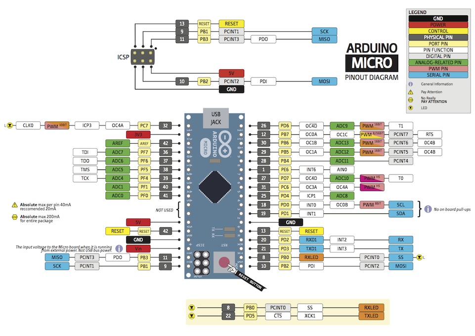
- Digital I/O Pins: The board boasts 20 digital I/O pins that can be configured as either inputs or outputs. These pins operate on a binary system, capable of being set to either a HIGH state (5V) or a LOW state (0V). This flexibility allows for digital communication, interfacing with sensors, controlling actuators, and more.
- Analog Pins: The Arduino Micro offers 12 analog pins that facilitate analog input. These pins have a 10-bit Analog-to-Digital Converter (ADC), allowing them to receive a range of values. Unlike digital pins, which have only two states, analog pins can detect and measure a multitude of levels, providing greater precision and sensitivity in applications such as sensor readings.
- PWM Pins: This board features 7 Pulse Width Modulation (PWM) pins, denoted by numbers 3, 5, 6, 9, 10, 11, and 13. PWM allows the board to simulate analog output by modulating the width of the signal's pulse. Each PWM pin provides an 8-bit resolution, meaning it can produce 256 different levels of analog-like output. This is useful for controlling motors, dimming LEDs, and generating precise signals.
- UART Pins: The Arduino Micro supports UART (Universal Asynchronous Receiver-Transmitter) communication through its Rx (Receive) and Tx (Transmit) pins. These pins enable serial data transmission and reception, making it possible to communicate with other devices or establish connections to external modules.
- SPI Pins: With the inclusion of Serial Peripheral Interface (SPI) pins, the Arduino Micro facilitates communication between the microcontroller and devices such as sensors and shift registers. SPI utilizes two pins: MOSI (Master Output Slave Input) and MISO (Master Input Slave Output), enabling bidirectional data transfer and synchronization between the microcontroller and connected peripherals.
- I2C Pins: Two dedicated pins, SDA (Serial Data) and SCL (Serial Clock), support the I2C (Inter-Integrated Circuit) communication protocol. I2C is a two-wire interface that facilitates simple and efficient data exchange between multiple devices on the same bus. The SDA pin handles data transmission, while the SCL pin ensures synchronized timing for accurate communication.
-
Power Pins: The Arduino Micro includes several power-related pins:
- VIN: This pin serves as the input voltage pin, allowing the board to be powered through an external power source or the power jack. It can handle voltages up to 12V.
- VCC: This pin supplies power to the onboard ATmega32U4 microcontroller, operating at a regulated 5V. When powered through the 'RAW' pin or USB, it can also serve as an output to power other devices.
- RS (Reset): By connecting this pin to the ground, you can initiate a reset of the Arduino Micro, restarting its operation. The board remains inactive until the reset line is returned to a high state.
- GND: The ground pin provides the common reference voltage (0V) for the entire system.
- AREF: The AREF pin serves as a reference voltage for the analog inputs, ensuring accurate analog measurements. It is used in conjunction with the analogReference() function.
-
Inbuilt LED (13): The Arduino Micro features a built-in LED (Green) connected to digital pin 13. This LED can be controlled by switching the pin to a HIGH state to turn it on or a LOW state to turn it off. It is often used for quick visual feedback in projects.
-
Micro USB Port: The Arduino Micro is equipped with a Micro USB 2.0 port, allowing seamless connectivity between the board and your computer. This port serves as a bridge, enabling data transfer, power supply, and programming functionalities. By simply connecting the board to your computer using a micro USB cable, you can upload code, communicate with the board, and power it without the need for additional power sources.
Applications:
- Robotics: The Arduino Micro's digital and analog I/O pins, PWM capability, and communication interfaces make it an excellent choice for building robots. It can be used to control motors, read sensor data, implement obstacle avoidance algorithms, and enable wireless communication for remote control or autonomous operation.
- IoT (Internet of Things): With its compact size and built-in USB functionality, the Arduino Micro is ideal for IoT projects. It can be used to gather data from various sensors and transmit it to the cloud, control connected devices, and create interactive IoT prototypes and applications.
- Human-Computer Interaction (HCI): The ability of the Arduino Micro to function as a keyboard or a mouse opens up opportunities for HCI applications. You can create custom input devices, control multimedia applications, automate tasks, and develop interactive installations that respond to user input.
- Home Automation: The Arduino Micro can be the brain behind home automation projects. It can control lighting systems, monitor environmental conditions, integrate with voice assistants, and enable remote access and control of devices within a smart home setup.
- Wearable Technology: Due to its small form factor, the Arduino Micro is well-suited for wearable tech projects. It can power and control sensors, display information on small screens, monitor biometric data, and interact with other devices to create innovative wearable gadgets and accessories.
- Educational Projects: The Arduino Micro's user-friendly nature, extensive online resources, and compatibility with the Arduino IDE make it an excellent educational tool. It can be used to teach electronics, programming, and physical computing concepts, fostering hands-on learning and experimentation.
- Prototyping and Product Development: The Arduino Micro is often employed in the early stages of prototyping and product development. Its flexibility, expandability, and compatibility with various shields and modules allow for rapid development and iteration of proof-of-concept models and product prototypes.
Circuit:
We will not need any circuit, in this testing code, we will print out byte values in all possible formats on the serial monitor.
Connecting with Arduino First Time
- Open the Arduino IDE: Download the Arduino IDE from the software page if you haven't done so already. The Arduino IDE is the software environment where you write and upload your code. Arduino IDE Download: Arduino IDE
- Connect the board to your computer: Using a data USB cable (not a charge-only cable), connect the Arduino Micro board to your computer. This provides power to the board and allows the IDE to communicate with it.
- Select the Board: In the Arduino IDE, click on "Tools" in the menu bar, and then locate the "Board" row. If a board is already selected, it will be displayed there. Hover over the "Board" row to see the installed board packages. Select the "Arduino Micro" board from the list.
- Select the Port: In the Arduino IDE, click on "Tools" in the menu bar, and find the "Port" row. This displays the currently selected port. Select the serial device of your Arduino Micro board from the "Tools | Serial Port" menu.
- Upload a Sketch: Copy your code into the Arduino IDE. If desired, click the "Verify" button to check for any compilation errors. Once verified, click the "Upload" button to program the board with your sketch.
After uploading, your sketch will start running on the board, and it will continue running every time the board is reset. To view the output or debug your code, you can open the Serial Monitor in the Arduino IDE by clicking on the icon in the upper right corner.
Now you're ready to unleash the capabilities of your Arduino Micro board and bring your projects to life!
Please note that you may need to refer to the official Arduino documentation or user guides for specific troubleshooting or detailed instructions: Arduino Documentation
Code:
A code example that blinks an LED and displays the blinking status on the Serial Monitor for an Arduino board the Onboard-LED is connected to pin 13. The LED will blink on and off at a frequency of 1 second (1000 milliseconds). The status of the LED (ON or OFF) is displayed on the Serial Monitor.:
// LED pin
const int ledPin = 13;

// Blink interval
const int blinkInterval = 1000; // 1 second

// Variables
bool ledState = false;
unsigned long previousMillis = 0;

void setup() {
  pinMode(ledPin, OUTPUT);
  Serial.begin(9600);
}

void loop() {
  // Get the current time
  unsigned long currentMillis = millis();

  // Check if it's time to blink the LED
  if (currentMillis - previousMillis >= blinkInterval) {
    // Save the current time for the next iteration
    previousMillis = currentMillis;

    // Toggle the LED state
    ledState = !ledState;
    digitalWrite(ledPin, ledState);

    // Print the blink status on Serial Monitor
    if (ledState) {
      Serial.println("LED ON");
    } else {
      Serial.println("LED OFF");
    }
  }
}
-
Pin and Interval Setup:
- The code defines the LED pin (13) and the blink interval (1000 milliseconds, or 1 second).
- Variables are declared to store the LED state (ON or OFF) and the previous time the LED changed state.
-
Setup Function:
- In the
setup()function, the LED pin is configured as an output usingpinMode(). - Serial communication is initiated with a baud rate of 9600 using
Serial.begin().
- In the
-
Loop Function:
- The
loop()function is executed repeatedly. - The current time in milliseconds is obtained using
millis()and stored in thecurrentMillisvariable.
- The
-
Blinking LED:
- The code checks if the elapsed time since the last LED state change is greater than or equal to the blink interval.
- If the condition is true, it means it's time to toggle the LED state.
- The LED state is inverted using the logical NOT operator (
!) and assigned to theledStatevariable. - The
digitalWrite()function sets the LED pin to the current state ofledState, either HIGH (ON) or LOW (OFF).
-
Status Display:
- After changing the LED state, the code prints the blink status on the Serial Monitor.
- If the LED is ON (
ledStateis true), it prints "LED ON". - If the LED is OFF (
ledStateis false), it prints "LED OFF".
-
Repeat:
- The code loops back to the beginning of the
loop()function and repeats the process.
- The code loops back to the beginning of the
Technical Details:
| Board | Name | Arduino® Micro |
|---|---|---|
| Microcontroller | ATmega32u4 | |
| USB connector | Micro USB | |
| Pins | Built-in LED Pin | 13 |
| Digital I/O Pins | 20 | |
| Analog input pins | 12 | |
| PWM pins | 7 | |
| Communication | UART | Yes |
| I2C | Yes | |
| SPI | Yes | |
| Power | I/O Voltage | 5V |
| Input voltage (nominal) | 7-12V | |
| DC Current per I/O Pin | 10 mA | |
| Clock speed | Processor | ATmega32U4 16 MHz |
| Memory | ATmega328P | 2.5KB SRAM, 32KB FLASH, 1KB EEPROM |
| Weight | 13 g | |
| Width | 18 mm | |
| Length | 48 mm | |
Resources:
- You might also want to look at: the reference for the Arduino language.
- Getting Started
Comparisons:
The Arduino Micro and Arduino Pro Micro are two similar development boards with some differences:
- Microcontroller: Both boards are based on the ATmega32U4 microcontroller, which is the same chip used in the Arduino Leonardo.
- Size: The Arduino Micro is slightly larger than the Arduino Pro Micro. The Micro has dimensions of 48mm x 18mm, while the Pro Micro is smaller at 33mm x 18mm.
- I/O Pins: The Arduino Micro has 20 digital I/O pins (including 7 PWM outputs) and 12 analog inputs. On the other hand, the Arduino Pro Micro provides 18 digital I/O pins (including 7 PWM outputs) and 8 analog inputs.
- Voltage: The Arduino Micro operates at a voltage of 5V, while the Arduino Pro Micro gives you the option to choose between 5V and 3.3V versions depending on your project's requirements.
- USB Connectivity: Both boards feature a micro USB connector for connection to a computer. However, the Arduino Micro has built-in USB functionality, while the Arduino Pro Micro requires an additional USB-to-Serial converter chip for USB communication.
- Programming: Both boards can be programmed using the Arduino IDE and are compatible with the same programming language.
- Additional Features: The Arduino Pro Micro offers a few additional features compared to the Micro. It has onboard reset and status LEDs, and some versions of the Pro Micro include a built-in voltage regulator.