AED 12.60
Description
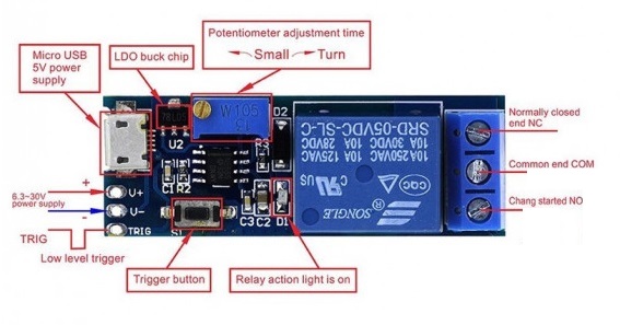
Micro USB Power Adjustable Delay Relay Timer Control Module Trigger Delay Switch 5-30VBy adjusting the potentiometer can set the length of time. MicroUSB 5.0V power supply with an input port which makes it easy to use works in a wide supply voltage range of 5v ~ 30V
Package Includes:
-
1 x NE555 Delay Switch Module USB
Features:
- MicroUSB 5.0V power supply with an input port, easy to use
- 5 ~ 30V wide supply voltage
- External signal trigger and key trigger in two ways
- With a Relay indicator
- Anti-interference ability, the Relay at various interference will not misoperation, suitable for industrial control
- the delay time is adjustable, (0 ~ 24.2 seconds)
- Adding a resistor to the potentiometer can increase the delay time
- You can add capacitor C1 which can increase latency time
- with input power light, Relay and Power LED
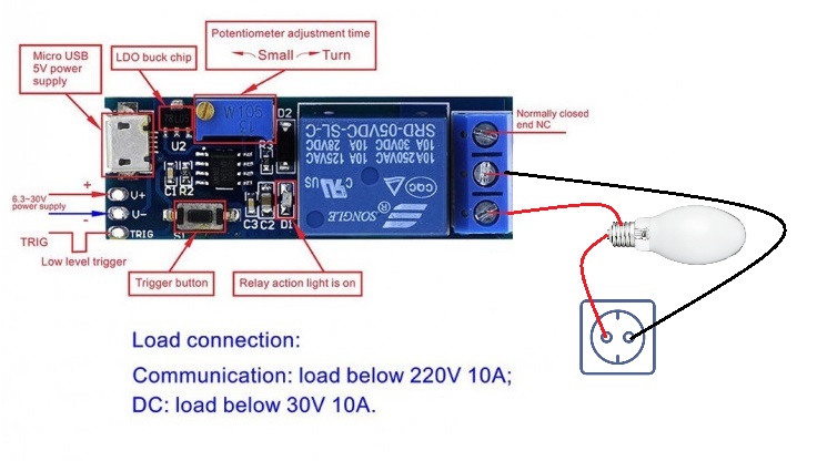
- can control the device with AC 220 v / 10 or below. (maximum control equipment 2200W)
Description:
Micro USB Power Adjustable Delay Relay Timer Control Module Trigger Delay Switch 5-30VThe length of time can be set by adjusting the potentiometer. MicroUSB 5.0V power supply with an input port for convenience. It operates in a wide supply voltage range of 5 30V and has two ways to trigger an external signal and a key. The Relay is equipped with an LED indicator. Anti-interference capability, the Relay will not operate incorrectly in the presence of various interferences, making it suitable for industrial control.
Principle of Work:
Module outputs: normally open (NO) and the common terminal (COM) are disconnected, normally closed (NC) and the common terminal (COM) is connected. Providing a low pulse signal, or touch trigger key, Relay, and indicator lights, the output of the state: normally open (NO) and common terminal (COM) connected, normally closed (NC), and common terminal (COM) disconnected. After 0-24 seconds (this time can be adjusted to your needs), turn off the relay and return to the state before the trigger.
Potentiometer-adjusted timing length, default 0-24 seconds. If you require additional time, replace the larger capacitor (C2) or potentiometer. T is the delay time. For example, if you have a 22uf capacitor and a 1M resistor, T = 1.1 * 0.000022 * 1000000 = 24.2 seconds.
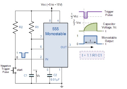
When a negative ( 0V ) pulse is applied to the trigger input (pin 2) of the Monostable configured 555 Timer oscillator, the internal comparator, (comparator No1) detects this input and “sets” the state of the flip-flop, changing the output from a “LOW” state to a “HIGH” state. This action in turn turns “OFF” the discharge transistor connected to pin 7, thereby removing the short circuit across the external timing capacitor, C1.
This action allows the timing capacitor to start to charge up through resistor, R1 until the voltage across the capacitor reaches the threshold (pin 6) voltage of 2/3Vcc set up by the internal voltage divider network. At this point, the output of the comparator goes “HIGH” and “resets” the flip-flop back to its original state which in turn turns “ON” the transistor and discharges the capacitor to ground through pin 7. This causes the output to change its state back to the original stable “LOW” value awaiting another trigger pulse to start the timing process over again. Then as before, the Monostable Multivibrator has only “ONE” stable state.
The Monostable 555 Timer circuit triggers on a negative-going pulse applied to pin 2 and this trigger pulse must be much shorter than the output pulse width allowing time for the timing capacitor to charge and then discharge fully. Once triggered, the 555 Monostable will remain in this “HIGH” unstable output state until the time period set up by the R1 x C1 network has elapsed. The amount of time that the output voltage remains “HIGH” or at a logic “1” level, is given by the following time constant equation.
t = 1.1R1C1
Where t is in seconds, R is in Ω, and C is in Farads.
Pinout of the Module:
Applications:
-
Vehicle equipment - delay preventing car ignition
- Burglar, alarm, building delay switch, sound, and light control light switch.
-
Sensitive home appliances: prevention of high sudden currents to burn components and devices.
Circuit:
Library:
This Module doesn't need a library to work.
Code:
Module is not MCU Based
Technical Details:
- Dimensions: 5.4 * 1.9 * 1.8cm (L * W * H).
- Weight: 16g.
- Application Voltage: AC 220v
- Max Relay Current:10A
- Maximum Equipment Controlled Power: 2200W
- Main Chip: NE555
- Control Voltage: 5~30
Resources:
Comparisons:
This is a basic timer based on 555 which can give a specific and accurate time in a small amount (in seconds) of time but in the higher periods you might start getting errors depending on the error value of the cap and the resistors
if you need to make your own timer that is accurate and have the ability to adjust the time in week and seconds you would need any Arduino board + DS1302 RTC module + Relay module with this set of components you can make a timer with outputs more than one specific for your application all the items available on our website feel free to search and pick your favorite.