AED 12.60
Description
The D4184 N-Channel logic compatible MOSFET with low Rds(on) is used in this MOSFET module with optoisolation for moderate to higher current low-side switching applications.
Package Includes:
- D4184 MOSFET Control Module
- 3-pin Screw Terminal
- 2-pin Screw Terminal
- The small male header strip
Features:
-
The modules utilize the D4184 N-channel MOSFET that has a low Rds(on) resistance of 8.5mΩ typical.
-
These modules support about 10A of continuous current with a load voltage of 12V. If driven with PWM, the maximum peak current can be greater up to 20A or more.
-
The design of these modules includes an optoisolator on the input so the input is biased from the output load voltage and is independent of logic levels used for the drive signal. A 3.3V input will drive as much current as a 5V input for instance.
-
Note that the module does not have a fly-back diode on the board. If using the module with inductive loads, an external fly-back diode should be used to avoid possible damage.
Description:
Mosfet The control signal and the power of the controlled device are insulated by the optocoupler isolation Module, which greatly increases the interference stiffness. 3V or 5V signal, compatible with any MCU and Arduino control board. PWM speed regulation, high start level, low stop level Control the starting and stopping of the engine, solenoid valves, and other ancillary equipment.
Principle of Work:
A PC817 optoisolator is included in the module to provide electrical isolation between the high-powered MOSFET side and the logic signals used to control the module. If something goes wrong and the MOSFET burns out, it should not harm the MCU that is controlling it. The module's MCU PWM input drives the internal LED side of the optoisolator. This input contains a 1K ohm series current limiting resistor to keep the current through the LED at safe levels, allowing the input to be driven by up to a 20V input or even higher if an MCU is not used. When the PWM input signal is low or disconnected, the internal LED in the optoisolator turns off, keeping the phototransistor output disabled. A 4.7K resistor pulls the gate of the MOSFET to the ground when the phototransistor is turned off. The MOSFET remains turned off, and the load is disconnected from the ground and disabled.
A logical high on the PWM input activates the internal optoisolator LED, which in turn activates the phototransistor. This results in a voltage divider made up primarily of two 4.7K resistors. This biases the gate at 50% of the power supply voltage, causing the MOSFET to turn on. The gate will be at 6V if a 12V power supply is used. Because the maximum gate voltage available to turn on the MOSFET is 50% of the power supply voltage, the power supply must be at least 6V. Lower power supply voltages cause more power dissipation in the MOSFET, so a minimum power supply of 9V is recommended if drawing more than a few amps through the module. When the MOSFET conducts, the load is connected to the ground to complete the circuit, and power is applied to the load. This also serves as a ground for the onboard LED, which illuminates when the MOSFET is turned on. Over the 6-36V operating range, a 4.7K resistor limits the current through the onboard LED to safe levels.
Pinout of the Module:
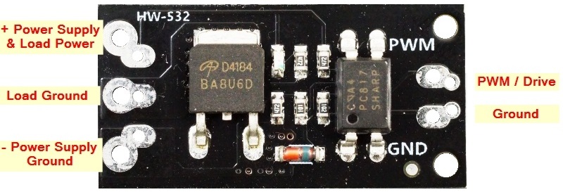
Logic Signal Connections: The 2-pin connector on the right side is for making connections to the MCU. It has two holes on 4mm centers that support a 2-position screw terminal as well as two holes on 0.1″ centers that can alternatively support a standard male header which may be handy in a breadboard setup. The pins are labeled PWM for the signal and GND for the signal ground.
DC Load Power Supply: is connected to the 3-pin screw terminals marked + / LOAD / – on the back of the module. The positive lead of the power supply connects to + and the ground connection is hooked up to –. The module supports a load power supply of 6-36VDC
Load: The load which is being driven is connected to the screw terminals marked + and Load on the back of the module. The positive lead of the load connects to the + terminal and the negative lead of the load connects to the – terminal.
The signal ground and the load ground connections are not connected together on the module due to the optoisolator being used to provide isolation between the MOSFET power circuit and the MCU.
1 x 2 Screw Terminal / Header (Logic Signal Input)
- PWM = Signal input (active HIGH).
- GND = Signal ground
1 x 3 Screw Terminal (Load Power Supply Connections)
- + = Connect to the power supply (6-36V) being used to power the load
- – = Connect to power supply ground
1 x 3 Screw Terminal (Load Connections)
- + = Connect to the positive lead of load (motor, LEDs, fan, etc)
- LOAD = Connect to the negative lead of load
Applications:
- LED Dimming
- Motor speed control
Circuit:
To get this circuit to work you will need a PWM source, you could use an Arduino with Pot and program one of the board PWM pins to act like a PWM source. with this set up you will be able to control a motor or LED strip with a voltage between 6 and 36v.

Library:
This Module doesn't need a library to work.
Code:
void setup() {
pinMode(3,1);
}

void loop() {
int a = analogRead(A0);
analogWrite(3,a/4);
delay(50);
}
Technical Details:
-
Module Size: 23mm x 16mm
-
40V 50A
-
2x 2mm screw holes,
-
Distance between the holes 8mm
Resources:
Comparisons:
These modules work well for basic ON/OFF operation such as for driving a solenoid or PWM control such as for dimming an array of LEDs and can handle a surprising amount of power given a small size. It is also possible to parallel these modules to further increase the power handling capability. Though the maximum current spec for the MOSFET is 50A, do not expect to run 50A through this small module as it will quickly overheat due to the minimal heatsink capability of the small PCB, the IRF520 module works exactly the same as this module but the only difference that it doesn't include an optocoupler that means there is no real isolation between the input and the output which might damage the MCU in some cases that is and advantage to our Item