AED 8.40
Description
The LM358 100 gain Amplification Module Operational Amplifier Module is based on the LM358 operational amplifier, a high-gain, frequency-compensated operational amplifier made to run across a broad variety of voltages from a single power source. It is utilized in traditional operational amplifier circuits that require a single power rail for operation.
Package Includes:
- 1 x Amplifier Module LM358 100 Times Signal Gain
Features:
-
On-board LM358 chip
-
Adjustable gain up to 100x
-
On-board 10K adjustable resistor for gain adjustment
-
On-board power indicator
-
Chip has been drawn out to the main pins for direct input and output of signals
Description:
The LM358 operational amplifier, a high-gain, frequency-compensated operational amplifier designed to operate across a wide range of voltages from a single power source, is the basis for the LM358 100-gain Amplification Module Operational Amplifier Module. It is used in conventional operational amplifier circuits, which function only with a single power rail. It contains a built-in LED power indicator and a 10K adjustable resistor for gain adjustment. The LM358 operational amplifier module comes in handy for projects that require simple waveform amplification, such as amplifying a microphone signal. In terms of simple amplification jobs involving moderate frequency signals, such as microphone inputs, these assemblies perform pretty well. We were able to change the output over the entire range of 10mV to 1V without noticeably introducing distortion when using a 10mV 1KHz input. Since the LED has a 1K current-limiting resistor and the LM358 can withstand voltages of up to 32V, the LED will be powered at its maximum current of 20mA at roughly 22V. If utilizing the module at higher voltages, the LED can be deleted, or the 1K resistor at R10 can be upgraded to 2.2K or 4.7K.
Principle of Work:
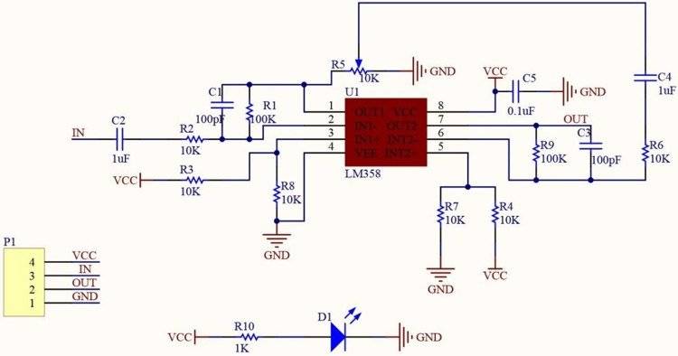
Use this module by applying a voltage of 5 to 12 VDC to the device's VCC pin. Connect the sensor's signal output to the Sig. Take the amplified output from the Sig. Out pin and connect it to the module's input pin. The multi-turn potentiometer on the module can be used to control the gain, which has a range of 1x to 100x. Turning the pot CCW raises the amplification while doing the opposite with CW decreases it.
Pinout of the Module:
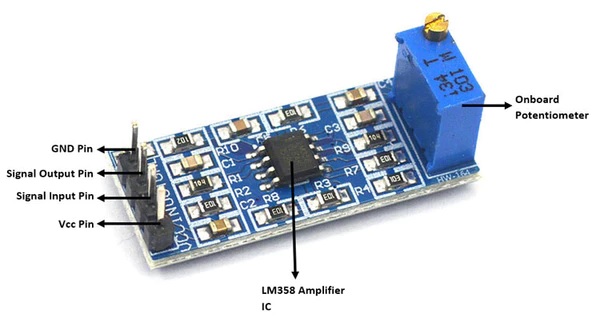
- VCC: 5V - 12V DC
- IN: analog input
- OUT: analog output
- GND: ground
Applications:
- It uses an amplifying instrument’s output voltage gain.
- Alarm clocks, traffic lights, light intensity meters, and burglar alarm circuits are a few further uses.
Circuit:
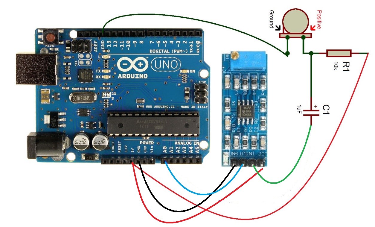
We are going to use a Microphone 9x7mm which is available on our website with the Amplifications module to form a Sound Detector circuit with is can be used with Arduino to detect any sound and then you can use it in any sound-based application.
We connected the output of the mice to the input of the amplifications module then the output of the module A0 pin of the Arduino and the VCC to Arduino 5v and the GND to GND.
Library:
No Library is needed for this module to function
Code:
When we handle sounds, we first must understand that the signal we obtain varies quickly and also has a lot of noise.
To do this, we define a time window of 50 ms, equivalent to a frequency of 20 Hz, and we calculate the maximum and minimum recorded within the window. Next, we show the value registered by serial port.
const int sensorPIN = A0;
const int sampleWindow = 50; // Ancho ventana en mS (50 mS = 20Hz)
void setup()
{
 Serial.begin(9600);
}
void loop()
{
 unsigned long startMillis= millis();
 unsigned int signalMax = 0;
 unsigned int signalMin = 1024;
 // Recopilar durante la ventana
 unsigned int sample;
 while (millis() - startMillis < sampleWindow)
 {
 sample = analogRead(sensorPIN);
 if (sample < 1024)
 {
 if (sample > signalMax)
 {
 signalMax = sample; //
 }
 else if (sample < signalMin)
 {
 signalMin = sample; //
 }
 }
 }
 unsigned int peakToPeak = signalMax - signalMin; // Amplitud del sonido
 double volts = (peakToPeak * 5.0) / 1024; // Convertir a tensión
 Serial.println(volts);
}
}
Technical Details:
- supply voltage: 5V-12V
- module dimensions: 32.7mm x 13.3mm
- Current Max Sink Current 20mA
- Current Max Sink Current 20mA Max Source Current 30mA
- Bandwidth 700kHz
Resources:
Comparisons:
Here we will try to compare a module based on LM358 like our module with another one based on the LM393 IC.
if you look at the table below you will notice that the input specs appear to be comparable, it is obvious that the LM358 Op-Amp has a lower bias current and offset voltage since these factors are important when used as an amplifier, which is where it is intended to be employed. In contrast, because a comparator is made to be used just to compare voltages rather than amplify them, the LM393 performs slightly worse in terms of input bias and offset performance. The substantial signal voltage gain also reflects this. To make the output transition as quick as feasible, the comparator's gain is substantially higher than the op-amp's, which has a much smaller gain. Since the comparator is not compensated, its bandwidth is also not stated.
|
Specification |
LM358 |
LM393 |
|
Supply Voltage |
32V, +/-16V |
36V, +/-18V |
|
Differential Input Voltage |
32V |
36V |
|
Input Offset Voltage |
3mV max. |
5mV max. |
|
Input Bias Current |
100nA max. |
250nA max. |
|
Input Common Mode Range |
0V to V+ - 2V |
0V to V+ - 1.5V |
|
Large Signal Voltage Gain |
100V/mV typ. |
200V/mV typ. |
|
Bandwidth |
1MHz |
Not specified |