AED 3.15
Description
The Photoresistor or LDR is used to estimate the brightness of a light source. In the presence of light, the resistance will be reduced, but in the absence of it, it will be increased. For the output, which controls the light intensity, you need an external resistor to use it with MCU and to get the analog voltage output. compatible with a variety of widely used microcontrollers, including Arduino, ESP32, and others.
Package Includes:
- 1 x LDR Photosensitive Resistor
Features:
- Uit is a sensitive photosensitive resistance sensor
- The Input voltage is 3.3V-5V
- The output form is analog voltage output using an external resistor as a voltage divider
- Sensitivity is High
- Simple & Small devices
- Easily used
- Inexpensive
- There is no union potential.
- The light-dark resistance ratio is high.
- Its connection is simple
Description:
The photoresistor or LDR The light sensor is a passive device that converts "light energy," whether visible or in the infrared range, into an electrical signal output. Light sensors are also known as "Photoelectric Devices" or "Photo Sensors" because they transform light energy (photons) into electricity (electrons). It is used to calculate the brightness of a light source. The resistance will be lowered in the presence of light, but raised in the absence of light. The input voltage range is 3.3V-5V. The output, which is regulated by the light intensity, requires an extra resistor to be used with an MCU and produce an analog voltage output. it is compatible with a broad range of popular microcontrollers such as Arduino, ESP32, and others. it is compatible with a broad range of popular microcontrollers such as Arduino, ESP32, and others.
Principle of Work:
Electrons are what causes electricity to flow through any metal, and they are classified as insulators, conductors, and semiconductors depending on how many electrons are passing through them at any given time. These are divided into groups based on the band gap, which is the energy difference between the valence band and the conduction band. Since there aren't many electrons accessible for conduction in a photoresistor, it is composed of high-resistance semiconductor material. The photoresistor's top is covered in a zigzag pattern made of the semiconductor cadmium sulfur. In order to obtain the necessary resistance and power rating, it is placed in this manner. When light strikes the photoresistor, the valence band electrons or valence electrons absorb energy sufficient for them to break their bond with the atom and move to the conduction band.
This process of transfer of electrons generates a current flow to the photoresistor and as more and more electrons transfer to the conduction band, the current flow increases and results in the decrease of resistance in the photoresistor.
Pinout of the Module:
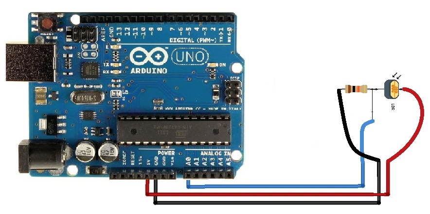
in order to work with this sensor you need to use 10kohm resistor and form this voltage divider circuit

| Circuit | Description |
|---|---|
| Output | Analog Out |
| VCC | +5V |
| GND | GND |
Applications:
- brightness measurement
- As a sensor for aligning solar cells
- The light barrier as counterpart for the laser
- Optocoupler as a remote station
Circuit:
The sensor GND to ground, sensor VCC connected to VCC, and sensor Output to Analog pin A0.
Library:
no library is needed.
Code:
The program measures the current voltage value at the sensor,
the resistance value of the sensor and outputs the results to the serial output
int sensorPin = A5; // Declare the input pin here
// Serial output in 9600 baud
void setup()
{
 Serial.begin(9600);
}
void loop()
{
 // Current voltage value is measured...
 int rawValue = analogRead(sensorPin);
 float voltage = rawValue * (5.0/1023) * 1000;
 float resitance = 10000 * ( voltage / ( 5000.0 - voltage) );
 // ... and here output to the serial interface
 Serial.print("Voltage value:"); Serial.print(voltage); Serial.print("mV");
 Serial.print(", resistance value:"); Serial.print(resitance); Serial.println("Ohm");
 Serial.println("---------------------------------------");
 delay(500);
}
We'll start obtaining data on the serial monitor when you upload the code, start the Serial Monitor, direct the sensor to a light source then check the serial monitor for changes
Technical Details:
- Operating voltage 3,3 V - 5 V
- Output voltage 3,3 V - 5 V
- Size: 5mm
- Fixed known resistance 10 kΩ
Resources:
Comparisons:
with this, you need external components which is a 10kohm resistor because you can't work directly with LDRs without a voltage divider circuit but still a very simple and cheap task, but still, this gives only analog output with no amplification or Schmitt trigger and digital output and it needs a breadboard to perform not like using a module which we have many version of them on our website you can use LDR in search to see them in our website.