AED 51.45
Description
The Keyestudio UNO R3 is a popular development board that utilizes the ATmega16U2 IC. With this IC, you benefit from increased memory and faster transmission rates, enabling efficient performance. The Keyestudio UNO R3 is widely recognized and widely used in the maker community. One of the great advantages of this board is its compatibility with various shields, which are additional boards that can be easily connected to expand the functionalities of the UNO board. This allows you to enhance your projects quickly and effortlessly. Additionally, the UNO board's pin headers are designed in a way that enables easy connectivity using Dupont wires. This feature provides flexibility and convenience when connecting different components and modules to the board.
Package Includes:
- 1 x R3 development board
- 1 * USB Cable
Features:
- Microcontroller: The board is equipped with the ATmega328 microcontroller, which provides reliable and efficient processing capabilities.
- Flash Memory: It has a generous 32KB of Flash memory, out of which 0.5KB is reserved for the bootloader. This allows you to store and run your program code smoothly.
- SRAM: The board offers 2KB of SRAM (Static Random-Access Memory), providing space for variables and data storage during program execution.
- EEPROM: With 1KB of EEPROM (Electrically Erasable Programmable Read-Only Memory), you can store and retrieve data that needs to be retained even when the power is turned off.
- Clock Speed: The board operates at a clock speed of 16 MHz, enabling fast and efficient execution of instructions.
- Digital I/O Pins: There are 14 digital I/O pins, including 6 pins capable of PWM (Pulse Width Modulation) output. This allows for precise control of devices such as motors, LEDs, and servos.
- Analog Inputs: The board features 6 analog input pins, enabling the connection and reading of analog sensors and devices.
- Voltage Switch: The board includes a voltage switch that allows you to easily toggle between 5V and 3.3V for the V pins, providing flexibility in connecting different components.
- Expanded Pinout: The 1.0 pinout design of the Keyestudio UNO R3 includes additional pins such as SDA and SCL for I2C communication. Two other new pins, IOREF, are placed near the RESET pin, allowing shields to adapt to the voltage provided by the board.
- Enhanced RESET Circuit: The board features a stronger RESET circuit, ensuring reliable and stable operations.
- Upgraded USB-to-Serial Chip: The ATmega16U2 replaces the ATmega8U2 found in earlier versions, providing improved USB-to-serial conversion for smoother communication with your computer.
Description:
The Keyestudio UNO R3 is an advanced development board designed to provide a robust platform for your projects. It features the ATmega328 microcontroller, offering excellent processing capabilities. With 32KB of Flash memory, you have ample space to store your program code, while the 2KB of SRAM allows for efficient data handling during program execution. Connectivity is a key highlight of this board. It boasts 14 digital I/O pins, including 6 pins capable of PWM outputs, enabling precise control over devices such as motors, LEDs, and servos. Additionally, the 6 analog input pins allow for the connection and reading of analog sensors and devices, expanding your project possibilities. The board operates at a clock speed of 16 MHz, ensuring speedy and efficient execution of instructions. Its 1.0 pinout design introduces additional features such as SDA and SCL pins for I2C communication and IOREF pins, which enable shields to adapt to the voltage provided by the board. This flexibility makes it easier to integrate various modules and components into your projects. Another notable feature is the voltage switch, which simplifies the process of toggling between 5V and 3.3V for the V pins. This versatility enables you to interface with different components and modules, accommodating their specific voltage requirements. The Keyestudio UNO R3 also incorporates an upgraded ATmega16U2 chip for enhanced USB-to-serial conversion, facilitating smooth communication with your computer. With a stronger RESET circuit, the board offers reliable performance and stability. Its ample memory capacity and powerful microcontroller empower you to create versatile and high-performance projects.
Principle of Work:
The Uno board follows the concept of Free Hardware, where its blueprints and specifications are openly available for anyone to replicate. This unique approach enables individuals and businesses to design their own boards based on the Arduino framework, allowing for customization while maintaining compatibility. Similarly, Free Software allows users to access and modify the source code according to their requirements. To facilitate the creation of applications for Arduino boards and provide a range of utilities, the Uno board seamlessly integrates with the Arduino IDE (Integrated Development Environment) platform. This platform serves as a programming environment, enabling users to write and upload their code, known as sketches. The Uno board features an onboard Serial Converter and an embedded bootloader, eliminating the need for an external programmer. This convenient setup allows users to easily program and upload code to the board. Furthermore, the Uno board leverages a wide range of libraries that can be downloaded online. These libraries provide pre-written code for various sensors and modules, offering a simplified programming experience. With the Uno board and these libraries, users can utilize an extensive array of sensors and modules without the need for in-depth knowledge of their internal workings.
The Uno board operates through a combination of hardware components and software processes. this is how the board works internally:
- Microcontroller: The heart of the Uno board is the ATmega328 microcontroller. It executes the instructions and performs the desired tasks based on the code uploaded to the board.
- Clock Speed: The microcontroller runs at a clock speed of 16 MHz. This clock determines the speed at which instructions are executed and data is processed.
-
Memory: The Uno board has three types of memory:
-
Flash Memory: This is where the program code (sketch) is stored. The ATmega328 has 32KB of Flash memory, of which 0.5KB is reserved for the bootloader. The code is uploaded to this memory using the Arduino IDE.
-
SRAM (Static Random-Access Memory): SRAM is used for storing variables and data during program execution. The Uno board provides 2KB of SRAM for this purpose.
-
EEPROM (Electrically Erasable Programmable Read-Only Memory): EEPROM is a non-volatile memory that can store data even when the power is turned off. The Uno board has 1KB of EEPROM capacity.
-
- Power Supply: The Uno board can be powered through a USB connection or an external power source. The voltage can range from 7 to 20 volts, although it is typically recommended to use 7 to 12 volts.
- Input/Output (I/O) Pins: The board features a range of digital and analog I/O pins. There are 14 digital pins, each of which can be configured as either an input or an output. Additionally, there are 6 analog input pins for reading analog values from sensors or other devices.
- Communication: The Uno board uses a USB-to-serial converter (usually the ATmega16U2 or ATmega8U2) to establish communication with the computer. This allows for uploading sketches and serial communication between the board and external devices.
- Bootloader: The Uno board includes a bootloader, which is a small program stored in the microcontroller's memory. The bootloader enables the board to receive code (sketch) uploads via the USB connection without the need for an external programmer.
- Arduino IDE: The Arduino IDE (Integrated Development Environment) is the software used to write, compile, and upload code to the Uno board. It provides a user-friendly interface for programming and offers a variety of libraries and functions to simplify the development process.
When a sketch is uploaded to the Uno board via the Arduino IDE, the microcontroller executes the instructions step by step, utilizing the available hardware resources, such as I/O pins and memory, to perform the desired tasks. The board interacts with external components, sensors, and modules based on the instructions in the code, enabling a wide range of applications and projects.
Pinout of the Module:
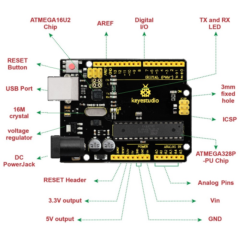
- ICSP (In-Circuit Serial Programming) Header: This header consists of MOSI, MISO, SCK, RESET, VCC, and GND pins, allowing for in-circuit programming of the microcontroller.
- Power LED Indicator: This LED indicates whether the board is correctly powered on. If the LED is off, it indicates a connection issue.
- Digital I/O: The UNO board provides 14 digital I/O pins, including 6 pins capable of PWM outputs. These pins can be used as both input and output to interface with various modules and devices.
- GND (Ground Pin Headers): These pins are used for circuit ground connections, ensuring proper grounding of components.
- AREF: AREF is the reference voltage (0-5V) for analog inputs. It is used with the analogReference() function.
- SDA and SCL: These pins are used for I2C communication, enabling connectivity with I2C devices.
- RESET Button: The RESET button allows you to reset the board, returning it to its initial state and restarting the program.
- D13 LED: The built-in LED on pin 13 is controlled digitally. When the pin is set to HIGH, the LED turns on, and when set to LOW, it turns off.
- USB Connection: The board can be powered via the USB connector by connecting it to a computer using a USB cable.
- ATMEGA 16U2-MU: This is the USB-to-serial chip that converts the USB signal into a serial port signal, facilitating communication with the computer.
- TX and RX LED: These LEDs indicate the transmit (TX) and receive (RX) activities when the board communicates via the serial port.
- Crystal Oscillator: The crystal oscillator helps the Arduino maintain accurate timekeeping and time-related functions. The Uno board uses a 16MHz crystal oscillator.
- Voltage Regulator: The voltage regulator controls the voltage provided to the board and stabilizes it for the microcontroller and other components.
- DC Power Jack: The board can also be powered externally using a DC power source (7-12V) connected through the DC power jack.
- IOREF: IOREF is used to configure the operating voltage of microcontrollers. In general usage, it is not frequently used.
- Analog Pins: The UNO board has 6 analog input pins (A0 to A5) that can read analog signals from sensors or function as digital pins when needed.
- Microcontroller: The microcontroller, such as the ATmega328 on the UNO board, serves as the brain of the board, executing instructions and controlling various functions.
Applications:
- Weighing Machines: The board can be integrated into weighing machines, allowing for precise and accurate measurements. With its digital and analog I/O pins, it can interface with load cells and other components to create a reliable weighing system.
- Traffic Light Count Down Timer: The UNO board can be used to develop count-down timers for traffic lights, providing clear and synchronized indications for drivers and pedestrians.
- Parking Lot Counter: By employing sensors and digital I/O pins, the board can be used to monitor and track the occupancy of parking lots, enabling efficient management and utilization of parking spaces.
- Embedded Systems: The UNO board serves as an excellent choice for building embedded systems. Its compact size, powerful microcontroller, and various I/O options make it ideal for creating custom electronic devices with specific functionalities.
- Home Automation: With its digital I/O and communication capabilities, the board can be integrated into home automation systems. It can control and monitor various devices, such as lights, appliances, security systems, and temperature sensors, offering convenience and energy efficiency.
- Industrial Automation: The UNO board is well-suited for industrial automation applications. It can be used to control and monitor processes, interface with sensors and actuators, and implement logic for machinery and equipment automation.
- Medical Instruments: The board can play a crucial role in the development of medical instruments and devices. It can be used to collect and process data from sensors, control actuators, and interface with displays, enabling the creation of advanced medical monitoring systems.
- Emergency Light for Railways: The UNO board can be employed to design emergency light systems for railway applications. It can control the illumination based on specific triggers or conditions, ensuring passenger safety during critical situations.
Circuit:
We will not need any circuit, in this testing code, we will rely on the built-in LED on the 13th pin.
Connecting with Arduino First Time
- Open Arduino IDE: If you haven't already, download Arduino IDE from the software page on the official Arduino website. This software will be your creative playground for writing and uploading code to your board. Here's the link: Arduino IDE Download
- Connect the board to your computer: Take a USB cable (make sure it's a data cable, not just for charging) and connect your board to your computer. This connection will not only power up the board but also establish a communication channel between the IDE and your board. Ensure the connectors fit both the board and your computer.
- Select the board: In Arduino IDE, click on the "Tools" menu in the menu bar and locate the "Board" row. If a board is already selected, you'll see its name displayed here. Hover over the "Board" row to see the available board packages. These packages include popular boards with their specific configurations. Click on the board that matches the one you have to select it.
-
Select the port: In the "Tools" menu, find the "Port" row. The currently selected port will be displayed here. Hover over the "Port" to reveal all the available ports. The naming convention for ports can vary based on your operating system. For example:
- Windows: COM3 (Arduino Uno)
- macOS: /dev/cu.usbmodem14101 (Arduino Uno)
- Linux: /dev/ttyACM0 (Arduino Uno)
Click on the port that corresponds to your board. If your board's port is already selected, no further action is needed.
Write a sketch, or use an Example Click the Verify button to try compiling the sketch and check for errors. Click the Upload button to program the board with the sketch.
Your sketch will start running on the board. It will run again each time the board is reset.
Code:
void setup() {
pinMode(13,1);
}
void loop() {
digitalWrite(13,1);
delay(1000);
digitalWrite(13,0);
delay(1000);
}
Technical Details:
- Input voltage (recommended): 7-12V
- Operating Voltage: 5 Volt
- Input Voltage: 7 to 20 Volts
- DC Current per I/O Pin: 20 mA
- DC Current for 3.3V Pin: 50 mA
- Length: 68.6 mm
- Width: 53.4 mm
- Weight: 25 g
Resources:
- the examples for using various sensors and actuators;
- the reference for the Arduino language;
- Video: http://video.keyestudio.com/ks0001/
Comparisons:
The Keyestudio UNO R3 is a compatible board that functions exactly like the Arduino Uno R3 board. In terms of functionality and capabilities, they are essentially the same. However, if we compare it to the SMD-compatible board available on the Keyestudio website (Keyestudio UNO R3 Upgraded) a distinguishing feature of the Keyestudio UNO R3 is the V pin. It has the ability to work with both 5V and 3.3V voltages by simply flipping the switch on the board. This flexibility allows you to adapt to different voltage requirements in your projects.
the Keyestudio UNO R3 remains fully compatible with the Arduino Uno R3 and offers additional features that can enhance your Arduino projects.