Out Of Stock
Description
Introducing the Pulse Sensor, an Arduino-compatible heart-rate sensor designed for easy integration into a wide range of projects. The sensor features an integrated optical amplifying circuit and noise elimination circuit, ensuring accurate readings. Ideal for students, artists, athletes, makers, and developers, this plug-and-play sensor provides real-time heart-rate data. Simply clip the sensor to your earlobe or fingertip and connect it to your Arduino.
Package Includes:
- 1 x Heart Rate Pulse Sensor Module Soldered Wire
Features:
- Accurate Heart Rate Monitoring: The module utilizes optical sensing technology to accurately detect and monitor the user's heart rate in real-time, providing reliable data for various applications.
- Plug-and-Play Compatibility: Designed to be compatible with Arduino and other microcontrollers, the sensor module can be easily connected and integrated into existing projects without the need for complex wiring or soldering.
- Pre-Soldered Wires: The module comes with pre-soldered wires, ensuring a secure and reliable connection. This eliminates the need for additional soldering work, making it convenient for both beginners and experienced users.
- Compact and Versatile: With its compact form factor, the sensor module can be seamlessly incorporated into a wide range of applications, including wearable devices, fitness trackers, health monitoring systems, and more.
- Low Power Consumption: The module operates with low power consumption, making it suitable for battery-powered applications. It ensures efficient energy usage and extends the battery life of portable devices.
- Integrated Amplifying and Noise Elimination Circuit: The sensor module features an integrated optical amplifying circuit and noise elimination circuit, enhancing the accuracy of heart rate measurements by minimizing interference and noise.
- User-Friendly Design: The front of the sensor module includes a heart logo where the user can place their finger for heart rate detection. It also includes a green LED for optimal signal detection and an ambient light photosensor for automatic brightness adjustment.
- Reverse Protection Diode: The module is equipped with a reverse protection diode to prevent any damage that may occur if the power leads are accidentally connected in reverse polarity.
Description:
The Heart Rate Pulse Sensor Module with Soldered Wire is a versatile and reliable device for accurate heart rate monitoring. This compact module utilizes advanced optical sensing technology to provide real-time heart rate data for a variety of applications. With its plug-and-play compatibility, it can be easily integrated into Arduino and other microcontroller projects without the need for complex wiring or soldering. The pre-soldered wires ensure a secure connection, making it convenient for users of all levels of expertise. The module features an integrated amplifying and noise elimination circuit, enhancing the accuracy of heart rate measurements by minimizing interference. Its low power consumption makes it suitable for battery-powered devices, maximizing energy efficiency. The user-friendly design includes a heart logo where the finger is placed for detection, along with a green LED for optimal signal detection and an ambient light photosensor for automatic brightness adjustment. With a reverse protection diode, the module offers added safety in case of accidental reverse polarity. Whether you're developing wearable devices, fitness trackers, or health monitoring systems, this module provides a compact, reliable, and efficient solution for precise heart rate monitoring.
Principle of Work:
The Heart Rate Pulse Sensor Module with Soldered Wire operates based on the principle of optical sensing to accurately measure and monitor the user's heart rate:
- Optical Sensing: The module uses an infrared LED and a photodiode placed in close proximity to the user's skin, typically on the fingertip or earlobe. The infrared LED emits light, which penetrates the skin and reaches the blood vessels.
- Blood Volume Changes: As the heart beats, blood volume in the vessels changes, causing variations in the amount of light reflected back to the photodiode. These fluctuations are directly related to the user's heart rate.
- Amplification and Filtering: The module incorporates an integrated amplifying circuit and noise elimination circuit. The amplifying circuit boosts the weak signals received from the photodiode, making them more discernible for measurement. The noise elimination circuit filters out unwanted external noise and interference, ensuring accurate readings.
- Signal Processing: The amplified and filtered signal is then processed by the module to extract the heart rate information. This process involves analyzing the variations in the intensity of the reflected light over time.
- Output: The processed heart rate data is made available through the module's output pins or communication interface, such as analog signals. This allows the data to be further processed, displayed, or transmitted to other devices for monitoring or analysis.
Pinout of the Module:

- VCC: This pin is used to supply power to the module. Typically connected to a 3.3V or 5V power source.
- GND: The ground pin, connected to the common ground of the system.
- Signal: The signal pin provides the heart rate data output from the module. It can be connected to an analog input pin of a microcontroller for data acquisition.
Applications:
- Health and Fitness Monitoring: The module can be used in wearable devices and fitness trackers to provide real-time heart rate monitoring during physical activities. It enables users to track their heart rate, analyze their workout intensity, and monitor their overall cardiovascular health.
- Medical Devices: The module finds applications in medical devices such as patient monitors, portable ECG machines, and pulse oximeters. It enables healthcare professionals to monitor patients' heart rates continuously and non-invasively, providing vital information for diagnosis and treatment.
- Biometric Authentication: The module can be utilized for biometric authentication systems. By measuring the user's heart rate, adds an extra level of security and ensures the uniqueness of the individual's physiological characteristics.
- Stress and Emotion Monitoring: The heart rate is closely associated with stress levels and emotional states. The module can be integrated into stress management devices or emotion recognition systems to monitor and analyze changes in heart rate, providing insights into the user's emotional well-being.
- Research and Development: The module serves as a valuable tool for researchers and developers working on projects related to human physiology, biofeedback, or human-computer interaction. It allows for the collection of heart rate data for analysis, experimentation, and algorithm development.
- Gaming and Virtual Reality: In the gaming and virtual reality industry, the module can be used to create immersive experiences that respond to the user's heart rate. It enables developers to incorporate real-time heart rate data into games, simulations, and virtual reality applications for enhanced interactivity.
- Internet of Things (IoT) Applications: With its compact size and low power consumption, the module can be integrated into IoT devices for remote heart rate monitoring. This can be useful in applications such as remote health monitoring, elderly care, and fitness coaching.
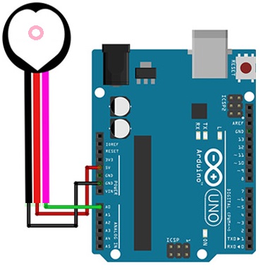
Circuit:
Library:
No need for a library for this module to work.
Code:
This is an example Arduino sketch that demonstrates the use of a Pulse Sensor to monitor and visualize heart rate data.
const int PulseSensorPurplePin = A0; // Connects the Pulse Sensor's PURPLE WIRE to ANALOG PIN 0
const int LED13 = 13; // Refers to the on-board LED of the Arduino

int Signal; // Stores the incoming raw data from the sensor. Signal value ranges from 0 to 1024
const int Threshold = 550; // Sets the threshold value to determine which Signal counts as a beat and which ones to ignore

void setup() {
pinMode(LED13, OUTPUT); // Sets the designated pin as the output for the heartbeat LED
Serial.begin(9600); // Establishes Serial Communication at a specific speed
}

void loop() {
Signal = analogRead(PulseSensorPurplePin); // Reads and assigns the value from the PulseSensor to the "Signal" variable
Serial.println(Signal); // Sends the Signal value to the Serial Plotter for monitoring

if (Signal > Threshold) { // If the Signal surpasses the threshold, the Arduino's on-board LED is turned on
digitalWrite(LED13, HIGH);
} else {
digitalWrite(LED13, LOW); // Otherwise, if the Signal is below the threshold, the LED is turned off
}

delay(10); // Adds a short delay for stability and responsiveness
}
- The code begins by defining two constants: "PulseSensorPurplePin" and "LED13". "PulseSensorPurplePin" represents the analog pin (A0) to which the Pulse Sensor's purple wire is connected, while "LED13" refers to the digital pin (13) connected to the on-board LED of the Arduino.
- In the "setup()" function, the pinMode() function is called to set the LED13 pin as an output, indicating that it will be used to blink in response to the heartbeat. Additionally, the Serial.begin() function is used to initialize serial communication with a baud rate of 9600.
- The "loop()" function is where the main functionality of the code resides. It repeatedly executes the following steps:
- a. Reads the analog value from the Pulse Sensor connected to the PulseSensorPurplePin using the analogRead() function. The raw analog value is stored in the "Signal" variable.
- b. Prints the "Signal" value to the Serial Monitor using the Serial.println() function. This allows you to monitor and visualize the raw heart rate data.
- c. Checks if the "Signal" value is above the defined "Threshold" value. If it is, the digitalWrite() function is used to turn on the LED13, indicating a detected heartbeat.
- d. If the "Signal" value is below the threshold, the digitalWrite() function is used to turn off the LED13, indicating no detected heartbeat.
- e. The code then includes a small delay of 10 milliseconds using the delay() function to ensure stability and prevent rapid execution.
Technical Details:
- Dimensions: 16 mm (diameter), 3 mm (overall thickness)
- Working Voltage: 3-5 V
- Working Current: 4 mA at 5 V
- Cable Length: 18 cm
- Connections: GND, VCC, analog signal out
Resources:
Comparisons:
When comparing the Heart Rate Pulse Sensor Module with Soldered Wire to the AD8232 Heart Rate Monitor module, there are several differences to consider:
- Functionality: The Heart Rate Pulse Sensor Module focuses solely on heart rate monitoring. In contrast, the AD8232 Heart Rate Monitor is a dedicated module designed specifically for heart rate monitoring and electrocardiography (ECG) measurements.
- Sensing Technology: The Heart Rate Pulse Sensor Module typically uses optical sensing technology with an infrared LED and a photodiode. The AD8232 module utilizes specialized ECG circuitry to measure the electrical activity of the heart through electrode pads.
- Output: The Heart Rate Pulse Sensor Module provides an analog signal output representing the detected heart rate. The AD8232 module outputs a digital signal that contains the processed ECG data, allowing for a more in-depth analysis of the heart's electrical signals.
- Signal Processing: The AD8232 module has built-in amplification, filtering, and noise cancellation circuitry to provide clean and reliable ECG signals. The Heart Rate Pulse Sensor Module may require additional external signal processing for advanced heart rate analysis.
- Applications: The Heart Rate Pulse Sensor Module is commonly used in wearable devices, fitness trackers, and health monitoring systems for real-time heart rate monitoring. The AD8232 Heart Rate Monitor module is suitable for medical applications, research, and development where detailed ECG data is required.
- Power Requirements: The Heart Rate Pulse Sensor Module typically operates at 3-5V and has a low working current. The AD8232 module also operates at a similar voltage range but may have different power consumption characteristics depending on the specific implementation.