AED 6.30
Description
This is the finest of the best rotary encoder; it is a high-quality 24-pulse encoder with detents and a pleasing feel. It may be panel mounted for use in a box or plugged into a breadboard (simply cut/bend the two mechanical side tabs). This encoder also has a pushbutton, allowing you to close a separate switch by pressing on the knob. One side contains a three-pin connection (ground and two coding pins) and the other has two normally-open switch pins.
Package Includes:
- 1 x Rotary Encoder Code Switch EC11
Features:
- These are rotary encoders that operate continuously.
- With an integrated push button switch (push to operate)
- Data input, like with current in-car CD players, volume and on/off control, or data
- selection through LED or LCD display are all possible.
Ideally suited for usage with PIC or ATMEL microcontrollers.
Description:
This is the finest of the best rotary encoder; it is a high-quality 24-pulse encoder with detents and a pleasing feel. It may be panel mounted for use in a box or plugged into a breadboard (simply cut/bend the two mechanical side tabs). This encoder also has a pushbutton, allowing you to close a separate switch by pressing on the knob. One side contains a three-pin connection (ground and two coding pins) and the other has two normally-open switch pins. Rotary encoders are found in a wide range of everyday gadgets. Rotary encoders are more common than we realize, appearing in everything from printers and photography lenses to CNC machines and robots. The volume control knob on a vehicle radio is the most common application of a rotary encoder in everyday life.
Principle of Work:
A slotted disc inside the encoder is linked to the common ground pin C. It also has two contact pins (A and B).
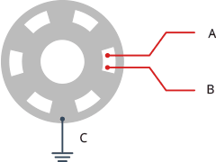
When you move the knob, A and B make contact with the common ground pin C in a specific order depending on which way you turn the knob.
Signals are formed when they come into touch with common ground. These signals are 90° out of phase because one pin makes contact with the common ground before the other. This is known as quadrature encoding.
When the knob is turned clockwise, the A pin connects to the ground before the B pin. When the knob is turned counterclockwise, the B pin connects to the ground before the A pin.
We can identify the way the knob is being spun by tracking when each pin connects to or disconnects from the ground. You may accomplish this by simply watching the condition of B when A changes.
If B does not equal A, the knob is rotated clockwise.

Clockwise rotation of the rotary encoder output pulses

If B Equals A, crank the knob counterclockwise.
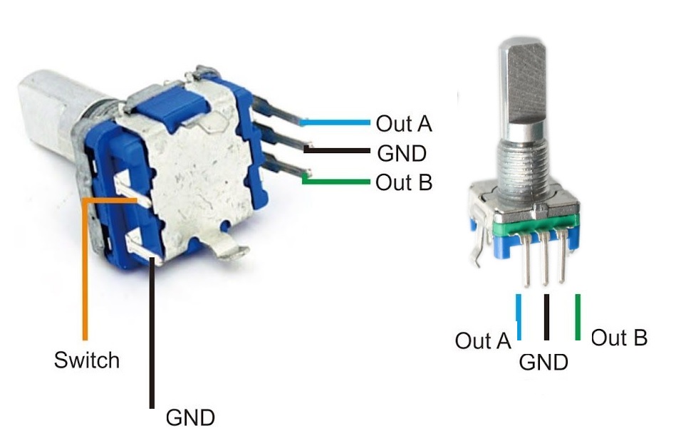
Pinout of the Module:
|
Pin Type |
Description |
|
OutA |
Encoder Pin A |
|
OutA |
Encoder Pin B |
|
Switch |
push-button switch |
|
GND |
Ground |
|
GND |
Ground |
Applications:
- Robotic arm controller
- Servo and Stepper motor control
- Precise motor movement
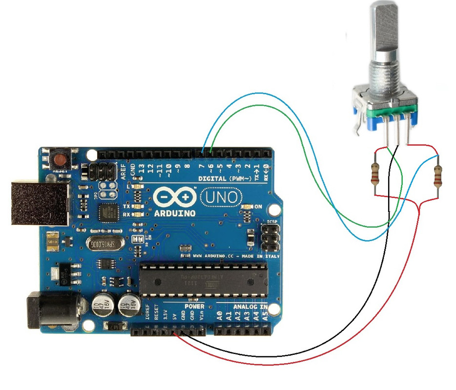
Circuit:
The Sensor Ground to Ground Pin outA and outB are connected to VCC through a 220ohm resistor and the connection point between the pins and the resistors are connected to pin 6 and 7 respectively.
Library:
no library is needed.
Code:
#define outputA 6
#define outputB 7

int counter = 0;
int aState;
int aLastState;

void setup() {
  pinMode (outputA, INPUT);
  pinMode (outputB, INPUT);

  Serial.begin (9600);
  // Reads the initial state of the outputA
  aLastState = digitalRead(outputA);
}

void loop() {
  aState = digitalRead(outputA); // Reads the "current" state of the outputA
  // If the previous and the current state of the outputA are different, that means a Pulse has occured
  if (aState != aLastState) {
    // If the outputB state is different to the outputA state, that means the encoder is rotating clockwise
    if (digitalRead(outputB) != aState) {
      counter ++;
    } else {
      counter --;
    }
    Serial.print("Position: ");
    Serial.println(counter);
  }
  aLastState = aState; // Updates the previous state of the outputA with the current state
}
We'll start obtaining data on the serial monitor when you upload the code, start the Serial Monitor, and start spinning the encoder. Each whole cycle, the module I have generates 30 counts.
Technical Details:
- Rotary Shaft Length: Approx. 12mm
- Shaft Full Length: Approx. 20mm
- Shaft Diameter: Approx. 6mm
- Size (L x W): Approx. 15 x 11mm
- Output: 2-bit gray code
- Closed Circuit Resistance: 3 ohms maximums
- Max. Rating: 10 mA @ 5 VDC
- Operating Temperature Range: -30 to 70 degrees Celsius
- Storage Temperature Range: -40 to 85 degrees Celsius
- Rotational Life: 30000 cycles minimum
- Switch Life: 20000 cycles minimum
Resources:
Comparisons:
Rotary encoders are the digital version of potentiometers, although they are more adaptable. Potentiometers can only revolve 3/4 of the circle whereas they can rotate 360° without halting. Potentiometers are employed in circumstances when the exact position of the knob is required. Rotary encoders, on the other hand, are employed when you need to know the change in position rather than the exact location. if we compare this rotary encoder to any other module we have on the website we see that we see that this encoder needs an external resistor to operate while we don't need any extra components when feeling with modules.