AED 25.00
Description
The KY-032 IR Sensor is a module that opens up a world of possibilities in obstacle avoidance technology. This sensor harnesses the power of infrared light to detect objects with remarkable precision. Its standout features include adjustable sensitivity and a broad range of 1 to 3 inches, thanks to the incorporated potentiometers. With these capabilities, the KY-032 IR Sensor is a versatile tool, suitable for a wide range of applications, from robotics to automation. In this introduction, we'll delve into the sensor's outstanding features, highlighting its adaptability and potential to enhance your projects.
Package Includes:
- 1 x Infrared IR Sensor Obstacle Avoidance Sensor KY-032
Features:
- Distance Adjustable: The KY-032 is a distance-adjustable infrared proximity sensor, offering a detection range from 2cm to 40cm. You can fine-tune the detection distance by turning the potentiometer knob.
- Wide Voltage Compatibility: It operates within a voltage range of 3.3V to 5V, making it compatible with various microcontrollers, including Arduino, ESP32, Teensy, ESP8266, Raspberry Pi, and more.
- Adaptability to Ambient Light: This sensor module exhibits strong adaptability to changes in ambient light conditions, ensuring reliable performance in different environments.
- Infrared Emitter and Receiver: The KY-032 consists of a pair of infrared LEDs, one serving as an emitter and the other as a receiver. The emitter sends out infrared light pulses at a specific frequency, and the receiver detects the reflections from obstacles.
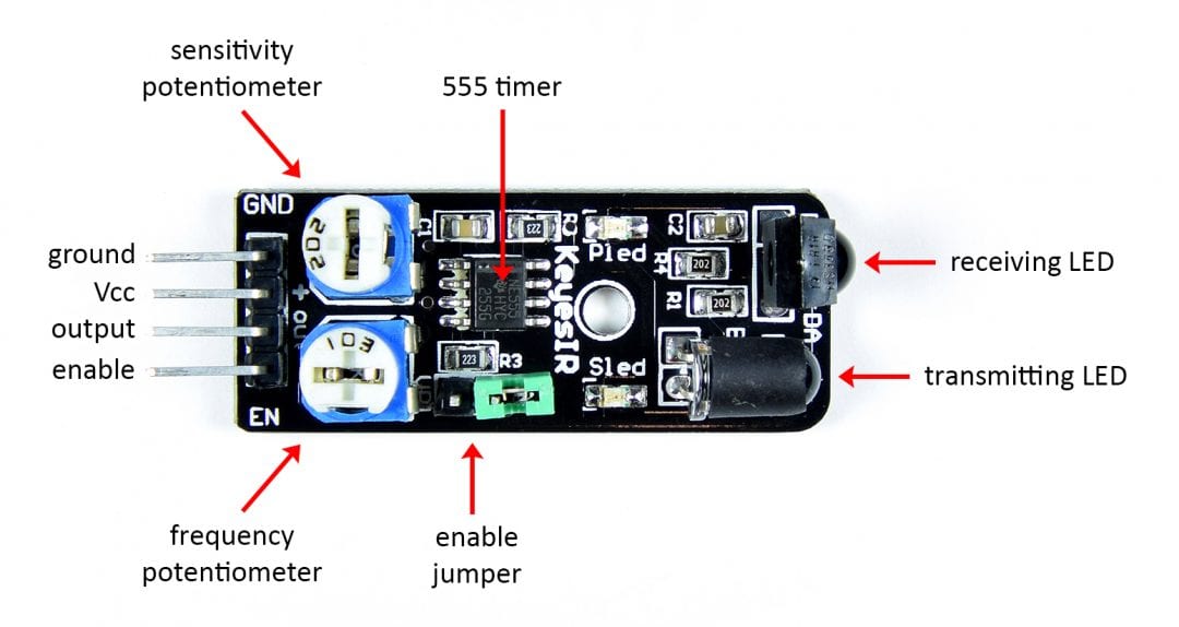
- Simple Pin Configuration: It has four pins - GND, + (positive voltage), S (output), and EN (enable). The module can be configured to operate continuously by using a jumper, or you can control its state by removing the jumper and utilizing the EN pin. A HIGH signal enables the sensor, while a LOW signal disables it.
- Distance and Frequency Adjustment: You can adjust the detection distance by turning the left knob, with the middle position offering the maximum distance. The right knob controls the frequency of the emitted IR pulse, ensuring compatibility with the receiver.
- Low Power Consumption: It operates with a working current of at least 20mA, making it energy-efficient for prolonged usage.
- Temperature Range: The KY-032 is designed to function in a temperature range from -10°C to 50°C (14°F to 122°F), making it suitable for both indoor and outdoor applications.
- Effective Angle: The sensor provides an effective detection angle of 35 degrees, allowing it to sense objects within its field of view.
- Compact Design: With dimensions of 1.6cm x 4cm (0.62in x 1.57in) and a weight of 9g, the KY-032 is a compact and lightweight module that can be easily integrated into various projects.
- TTL Level Output: The sensor's output signal is in the TTL (Transistor-Transistor Logic) level, where it produces a low signal when an obstacle is detected and a high signal when no obstacle is in its path.
- Adjustment Method: The KY-032 incorporates a multi-turn resistance adjustment method, allowing for precise fine-tuning of its sensitivity and range.
- IR Pulse Frequency: It operates at an IR pulse frequency of 38kHz, following the HS0038DB datasheet specifications.
Description:
The KY-032 Infrared Reflective Obstacle Sensor Module is a remarkable device, harnessing the power of infrared reflection to detect obstacles with precision. This sensor is designed with an ingenious setup, featuring an IR emitting LED and an IR photoreceptor positioned side by side. When an obstacle enters the sensor's range, it promptly responds by lowering the output to a low logic level and illuminating an onboard LED, signaling the presence of an obstacle. Diving deeper into its capabilities, the KY-032 operates effectively within a voltage range of 3.3 to 6VDC, making it highly versatile and compatible with a variety of microcontrollers. It boasts a specific operating frequency of 38KHz, and its oscillator circuit is driven by an NE555 timer, ensuring consistent and reliable performance. This sensor module incorporates not one, but two adjustable potentiometers, enhancing its adaptability. One of these potentiometers allows for precise control over the operating frequency, while the other governs the sensitivity of the detection distance, which spans an impressive range from 2cm to 40cm.
Principle of Work:
- Infrared Emitter (LED): The module consists of an infrared emitter, often in the form of an IR LED (Infrared Light Emitting Diode). This LED emits infrared light at a specific frequency, typically around 38KHz. The emitted light forms a beam and travels outward from the module.
- Infrared Photoreceptor (Receiver): Positioned adjacent to the IR emitter is an IR photoreceptor or receiver. This component is designed to detect infrared light, specifically the light emitted by the IR LED.
- Detection Process: When there is no obstacle within the range of the module, the emitted IR light travels freely and is not reflected to the photoreceptor. In this case, the photoreceptor does not receive a significant amount of IR light, and its output remains at a high logic level (HIGH).
- Obstacle Detection: When an obstacle, such as an object or a surface, enters the path of the emitted IR beam, it reflects some of the IR light back toward the receiver. This reflected light is detected by the IR photoreceptor, causing a change in its output. In the presence of an obstacle, the output signal switches to a low logic level (LOW).
Interaction with MCU:
- Connection: Connect the module to the MCU using jumper wires. The module has pins for ground (GND), positive voltage (+), signal output (S), and enable (EN). You can use the signal output pin (S) to connect to one of the digital input pins on the MCU.
- Voltage Supply: Provide the module with a suitable voltage supply, within the specified operating voltage range of 3.3V to 6VDC.
- Sensitivity Adjustment: You can use the trimpot on the module to adjust its sensitivity. Fine-tuning the sensitivity allows you to set the detection distance, typically ranging from 2cm to 40cm. This adjustment is crucial to adapt the module to different application requirements.
- Output Signal: The module provides an output signal, which is usually a digital signal. In the presence of an obstacle, the output goes LOW, and in its absence, it goes HIGH. You can read this signal using one of the digital input pins on the MCU.
- Enable Function: The module may have an enable pin (EN) that allows you to control its state. If you wish to keep the module always enabled, you can use a jumper to achieve this. If you want to control the module's operation dynamically, you can connect the EN pin to one of the digital output pins on the MCU. Sending a HIGH signal to EN enables the sensor, while a LOW signal disables it.
- Program the MCU: Write code for the MCU to read the module's output signal. Depending on whether the signal is LOW or HIGH, your MCU can trigger specific actions or responses. For example, you can program it to stop a robot when an obstacle is detected or turn on a warning light.
Pinout of the Module:
| Pin Name | Description | Additional Information |
|---|---|---|
| GND | Ground (0V) reference | Common reference point for the circuit. |
| + (Positive Voltage) | Positive voltage supply (Vcc), typically 3.3V to 6V DC | Powers the sensor module. |
| S (Signal Output) | Digital signal output (LOW in the presence of an obstacle, HIGH when no obstacle is detected) | Provides obstacle detection status. |
| EN (Enable) | Control pin to enable or disable the sensor module | Used to turn the module on or off. Some models may have a jumper for permanent enablement. |
Applications:
- Obstacle Avoidance in Robotics: One of the primary applications of this module is in robots for obstacle detection and avoidance. It can help robotic systems navigate their environment, avoid collisions, and follow predefined paths.
- Line-Following Robots: The module is often used in line-following robots that track lines on the ground. By detecting changes in surface reflectivity, these robots can stay on a designated path.
- Proximity Sensing: It can be employed for proximity sensing in various devices, such as automatic hand sanitizers, touchless faucets, or even in public restrooms to detect the presence of a user for automated flushing or handwashing.
- Security Systems: The module can be used in security systems to detect intruders or movement within a specified area. It can trigger alarms or surveillance cameras when an unexpected presence is detected.
- Smart Lighting Control: In smart home or industrial automation, the module can be used to control lighting systems. Lights can be turned on or off automatically when a person enters or leaves a room, conserving energy.
- Counting and Positioning: It's employed in applications where you need to count the number of objects passing through a specific area or determine the position of an object, such as in assembly lines or conveyor systems.
- Gesture Recognition: By carefully positioning the module, it can be used for recognizing hand gestures or interactions with electronic devices.
- Automatic Doors: In commercial buildings or retail stores, the module can be used to automatically open doors when someone approaches, providing convenience and accessibility.
- Interactive Displays: It can be integrated into interactive displays or kiosks that respond to user presence, making it useful in museums, trade shows, and information booths.
- DIY Projects: Hobbyists and makers often use this module in various do-it-yourself projects, from creating interactive art installations to customized automation solutions.
Circuit:
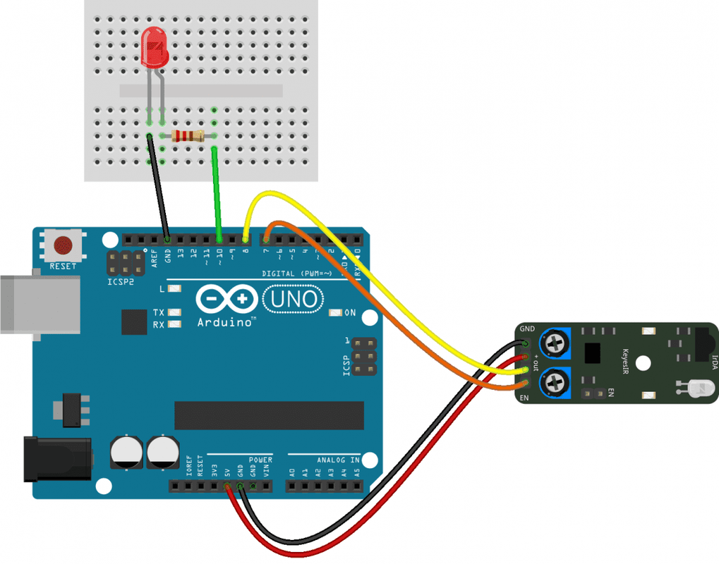
| Component | Arduino Pin | Connection |
|---|---|---|
| Infrared Sensor Module | Signal (S) | Connected to the sensor in (8) |
| Positive (+) | Connected to 5V (Vcc) | |
| Ground (GND) | Connected to GND (0V) | |
| EN Pin | Connected to enable pin (7) | |
| LED (Output Indicator) | Anode (Longer Leg) | Connected to ledPin (10) |
| Cathode (Shorter Leg) | Connected to GND (0V) via a current-limiting resistor (e.g., 220 Ohm) |
Library:
No library is needed for the module to work.
Code:
The code continuously monitors the output of the KY-032 sensor. When the sensor detects an obstacle, it turns on the connected LED. When there is no obstacle, it turns off the LED. This code essentially provides a visual indication of obstacle detection by illuminating the LED.
int sensorPin = 8;
int enablePin = 7;
int ledPin = 10;

void setup() {
  pinMode(sensorPin, INPUT);
  pinMode(enablePin, OUTPUT);
  pinMode(ledPin, OUTPUT);
}

void loop() {
  // Enable the sensor
  digitalWrite(enablePin, HIGH);

  // Read the sensor's output
  int val = digitalRead(sensorPin);

  // If an obstacle is detected, turn on the LED
  if (val == HIGH) {
    digitalWrite(ledPin, HIGH);
  }
  // If no obstacle is detected, turn off the LED
  else {
    digitalWrite(ledPin, LOW);
  }
}
-
Pin Configuration (Setup):
sensorPin (8): This pin is configured as an input and connected to the signal (S) pin of the sensor module. It reads the digital output from the sensor.enablePin (7): This pin is configured as an output and is connected to the enable (EN) pin of the sensor module. It's used to control the state of the sensor.ledPin (10): This pin is configured as an output and connected to an LED. The LED serves as an indicator to show the presence or absence of obstacles.
-
Loop Function (Runtime):
-
digitalWrite(enablePin, HIGH): This line of code sets the enablePin (EN) to HIGH, which enables the sensor module. In this state, the sensor is actively detecting obstacles. -
int val = digitalRead(sensorPin): This line reads the digital signal from the sensorPin (8). Thevalvariable stores the reading, which will be either HIGH (obstacle detected) or LOW (no obstacle detected). -
if (val == HIGH) { ... } else { ... }: This conditional statement checks the value ofval. Ifvalis HIGH, it means an obstacle is detected by the sensor, and the following actions occur:digitalWrite(ledPin, HIGH): The LED connected to ledPin (10) is turned on, indicating the presence of an obstacle.
-
If
valis LOW, indicating that no obstacle is detected, the following action occurs:digitalWrite(ledPin, LOW): The LED connected to ledPin (10) is turned off.
-
Technical Details:
- Operating Voltage: 3.3 to 6VDC
- Operating Current: 20mA
- Detection Distance: 2cm to 40cm
- Detection Range: 35 degrees
- Output Signal for Presence of Obstacle: Low Logic Level (LOW)
- Output Signal for Absence of Obstacle: High Logic Level (HIGH)
- Sensitivity Adjustment: Adjustable via Trimpot
- Operating Temperature Range: -10°C to 50°C
Resources:
- Fritzing Part: KY-032 IR Obstacle Avoidance Sensor Module.
- HS0038DB IR receiver datasheet.
- NE555 precision timer datasheet.
Comparisons:
The IR Infrared Obstacle Avoidance Sensor Module and the KY-032 Reflective Infrared Obstacle Sensor Module share some common features and principles, making them suitable for similar applications:
IR Infrared Obstacle Avoidance Sensor Module:
- Detection Range: 2-20cm.
- Detection Angle: 35º.
- Operating Voltage: 3-5V.
- Indicator Light: Features a red indicator light for visual confirmation when powered.
- Output Port Connectivity: Output directly connectable to the microcontroller's IO port.
- Adjustable Detection Distance: The detection distance can be adjusted via a potentiometer.
- Compact Size: Module size is 3.1 x 1.5cm.
KY-032 Reflective Infrared Obstacle Sensor Module:
- Detection Range: 2cm to 40cm.
- Detection Angle: 35°.
- Operating Voltage: 3.3-6VDC.
- Indicator Light: No specific mention of an indicator light.
- Output Port Connectivity: Output directly connectable to the microcontroller's IO port.
- Adjustable Detection Distance: The detection distance can be adjusted through a potentiometer.
- Module Size: Not explicitly specified but described as compact.
| Feature | IR Infrared Obstacle Avoidance Sensor Module | KY-032 Reflective Infrared Obstacle Sensor Module |
|---|---|---|
| Detection Range | 2-20cm | 2cm to 40cm |
| Detection Angle | 35º | 35° |
| Operating Voltage | 3-5V | 3.3-6VDC |
| Indicator Light | Red indicator light | Red indicator light |
| Output Port Connectivity | Connects directly to microcontroller IO port | Connects directly to microcontroller IO port |
| Adjustable Detection Distance | Yes, through a potentiometer | Yes, through a potentiometer |
| Module Size | 3.1 x 1.5cm | 4cm x 1.6cm |