AED 35.00
Description
The ADS1115 is a 16-bit analog-to-digital converter (ADC) that uses I2C communication protocol. It can be used to convert an analog voltage into a digital value that can be read and processed by a microcontroller. The module provides four input channels for connecting analog sensors and has a programmable gain amplifier to adjust the input range. The I2C interface allows multiple devices to be connected to the same bus, making it a suitable solution for systems that require multiple ADC inputs. The module operates at low power consumption and supports both single-shot and continuous conversion modes.
Package Includes:
- 1 x ADS1115 16-Bit Analog-To-Digital Converter
Features:
- 16-bit resolution for high precision in analog-to-digital conversion
- Four input channels for connecting analog sensors
- Programmable gain amplifier for adjusting input voltage range
- I2C communication protocol for multiple device connectivity on the same bus
- Supports both single-shot and continuous conversion modes
- Low power consumption, suitable for battery-powered applications
- Flexible input voltage range (0V to 3.3V or 0V to 5V)
- Versatile and reliable solution for a variety of applications.
Description:
The ADS1115 is a high-precision, 16-bit analog-to-digital converter (ADC) that operates using the I2C communication protocol. It converts analog signals from sensors into digital values that can be read and processed by a microcontroller. The module has four input channels for connecting various analog sensors and features a programmable gain amplifier that enables the input voltage range to be adjusted. This ADC supports both single-shot and continuous conversion modes, allowing it to be used in a wide range of applications. The I2C interface enables multiple devices to be connected to the same bus, making it a great choice for systems that require multiple ADC inputs. Additionally, the ADS1115 operates with low power consumption, making it suitable for battery-powered applications. With its 16-bit resolution and programmable gain amplifier, the ADS1115 provides a high level of precision in the conversion of analog signals to digital values. Its flexible input voltage range, I2C interface, and low power consumption make it a versatile and reliable solution for a variety of applications.
Principle of Work:
The ADC 16Bit ADS1115 I2C Analog to Digital Converter (ADC) operates on the principle of converting an analog voltage signal into a digital representation that can be processed and analyzed by a microcontroller or digital system. The ADC uses a successive approximation register (SAR) architecture to perform the conversion process.
The following steps describe the working principle of the ADC 16Bit ADS1115 I2C ADC:
- Sampling: The analog input voltage is sampled at a set interval, determined by the data rate setting of the ADC.
- Comparator: The ADC has an internal comparator that compares the sampled voltage to a reference voltage. The reference voltage is supplied by an internal or external voltage reference.
- Conversion: The ADC starts the conversion process by performing a binary search to determine the digital code that corresponds to the analog input voltage. The ADC compares the sampled voltage to the midpoint of the input voltage range, and based on the result, the search is narrowed to either the upper or lower half of the range. This process is repeated until the digital code representing the analog input voltage is determined.
- Digital Output: The ADC outputs the digital code representing the analog input voltage as a series of bits. The ADC has a programmable gain amplifier that allows the input voltage range to be adjusted, making it suitable for a variety of analog signals with different voltage levels.
- Communication: The ADC communicates the digital code to a microcontroller or digital system through the I2C interface. The I2C interface allows multiple ADCs to be connected to the same microcontroller or digital system and provides a simple, low-cost way to transfer the data.
Pinout of the Module:

- VDD: This pin is the power supply pin, and is typically connected to a voltage between 2V0 and 5V5.
- GND: This pin is the ground pin and is connected to a common ground.
- SCL: This pin is the clock pin for the I2C communication interface.
- SDA: This pin is the data pin for the I2C communication interface.
- ALERT/RDY: This pin is used to indicate that a conversion is complete and data is ready to be read.
- ADDR: This pin is used to set the I2C address of the ADC. By connecting the ADDR pin to either VDD or GND, the I2C address can be set to one of four possible values: 0x48, 0x49, 0x4A, or 0x4B.
- AIN0, AIN1, AIN2, AIN3: These are the multiplexed input pins of the ADC, and are used to connect the analog voltage signals to be converted.
Applications:
- Data acquisition: The ADC can be used to convert analog signals into digital form, which can then be processed by a microcontroller or computer.
- Sensors and transducers: The ADC can be used with sensors and transducers, such as temperature sensors, pressure sensors, and load cells, to convert the analog output of these devices into a digital signal that can be processed by a microcontroller or computer.
- Industrial control systems: The ADC can be used in industrial control systems to convert analog signals, such as temperature and pressure, into digital signals that can be used for control and monitoring purposes.
- Portable and battery-powered devices: The low power consumption of the ADC makes it well-suited for use in portable and battery-powered devices, such as portable data loggers and handheld devices.
- Robotics and automation: The ADC can be used in robotics and automation applications to convert analog signals from sensors into digital signals that can be processed by a microcontroller or computer for control and monitoring purposes.
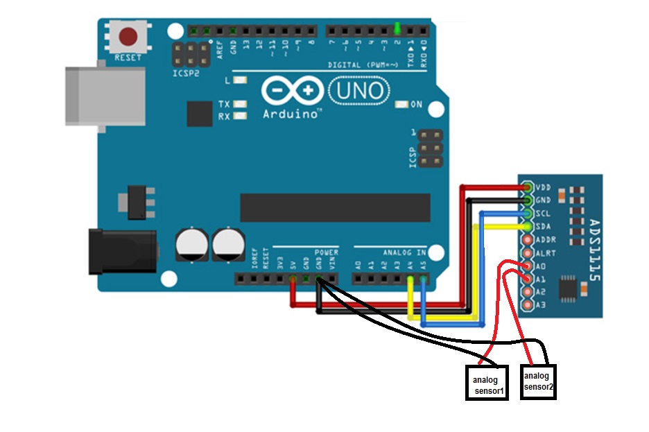
Circuit:
For our sample ADS1115 ADC and an Arduino code, the following connections must be made:
- SDA (ADS1115 Data) to A4 (Arduino)
- SCL (ADS1115 Clock) to A5 (Arduino)
- VDD (ADS1115 Supply Voltage) to 5V (Arduino)
- GND (ADS1115 Ground) to GND (Arduino)
- A0 (ADS1115 Analog Input 0) to the first analog input you want to read
- A1 (ADS1115 Analog Input 1) to the second analog input
Library:
- Open the Arduino IDE.
- Go to Sketch > Include Library > Manage Libraries.
- In the Library Manager, search for "ADS1115".
- Select the "Adafruit ADS1X15" library and click the "Install" button.
- Wait for the library to be installed.
- Close the Library Manager.
After the installation is complete, you can include the library in your sketch by going to Sketch > Include Library > Adafruit ADS1X15. You can now use the functions provided by the library to interact with the ADC.
Code:
#include "Wire.h"
#include "Adafruit_ADS1015.h"
Adafruit_ADS1115 ads;
void setup()
{
 Serial.begin(9600);
 Wire.begin();
 ads.begin();
 ads.setMode(ADS1115_MODE_SINGLESHOT);
 ads.setRate(ADS1115_RATE_250);
 ads.setGain(ADS1115_PGA_6_144V);
}
void loop()
{
 int16_t adc0, adc1, adc2, adc3;
 ads.startComparator_SingleEnded(0, 100);
 delay(1);
 while(ads.getConversionPending());
 adc0 = ads.getMilliVolts(0);
 ads.startComparator_SingleEnded(1, 100);
 delay(1);
 while(ads.getConversionPending());
 adc1 = ads.getMilliVolts(1);
 ads.startComparator_SingleEnded(2, 100);
 delay(1);
 while(ads.getConversionPending());
 adc2 = ads.getMilliVolts(2);
 ads.startComparator_SingleEnded(3, 100);
 delay(1);
 while(ads.getConversionPending());
 adc3 = ads.getMilliVolts(3);
 Serial.print("A0: "); Serial.print(adc0);
 Serial.print(" A1: "); Serial.print(adc1);
 Serial.print(" A2: "); Serial.print(adc2);
 Serial.print(" A3: "); Serial.println(adc3);
 delay(100);
}
The code reads voltage values from four analog inputs (A0 to A3) on an ADS1115 16-bit I2C ADC and displays the results in millivolts on the serial monitor. The ADC is connected to an Arduino using I2C communication. In the setup function, the ADC is initialized and its configuration such as sampling mode, rate, and gain are set. In the loop function, the ADC is triggered for each analog input, and the conversion result is read and converted to millivolts. The pollAlertReadyPin function is used to wait for the conversion to complete before reading the result. The resulting millivolt values are then displayed on the serial monitor.
Technical Details:
- Voltage Supply (VDD):
- 2V0 ~ 5V5
- Abs.Max VDD: -0.3V ~ 7V0
- Measurement range: -300mV ~ Vdd+300mV
- Interface: I2C
- I2C rate: 100kHz, 400kHz, 3.4MHz
- Resolution: 16 bits (±15 bits)
- Data rate: 8 ~ 860 SPS
- Number of multiplexed inputs: 4
- Active current: ~150uA (200uA max)
- Power down current: 0.5uA (2uA max)
- Offset error [1]: ±3 LSB
- Integral Non-Linearity (INL) [1]: 1 LSB
- Gain error [1],[2], @ 25°C: 0.01% (typ) 0.15% (max)
- I2C Addresses (selectable): 0x48, 0x49, 0x4a, 0x4b
- Operating temperature: -40°C ~ 125°C
Resources:
Comparisons:
The ADS1115 and ADS1015 are both analog-to-digital converters (ADCs) that operate using the I2C communication protocol. However, there are some key differences between the two:
- Resolution: The ADS1115 has a resolution of 16 bits, while the ADS1015 has a resolution of 12 bits. This means that the ADS1115 provides higher precision in analog-to-digital conversion compared to the ADS1015.
- Input Channels: The ADS1115 has four input channels, while the ADS1015 has three input channels. This allows the ADS1115 to accommodate more analog inputs compared to the ADS1015.
- Programmable Gain Amplifier: Both ADS1115 and ADS1015 have programmable gain amplifiers that allow the input voltage range to be adjusted. However, the ADS1115 has a more flexible gain range than the ADS1015.
- Data Rate: The ADS1115 has a wider range of data rates (8 ~ 860 SPS) compared to the ADS1015 (128 ~ 860 SPS).